- Basic Electronics - Materials
- Basic Electronics - Energy Bands
- Basic Electronics - Semiconductors
- Basic Electronics - Hall Effect
- Resistors
- Basic Electronics - Resistors
- Circuit Connections in Resistors
- Non-linear Resistors
- Basic Electronics - Linear Resistors
- Basic Electronics - Fixed Resistors
- Capacitors
- Basic Electronics - Capacitors
- Circuit Connections in Capacitors
- Variable Capacitors
- Basic Electronics - Fixed Capacitors
- Polarized Capacitors
- Inductors
- Basic Electronics - Inductors
- Basic Electronics - Inductance
- Circuit Connections in Inductors
- Types of Inductors
- Basic Electronics - RF Inductors
- Transformers
- Basic Electronics - Transformers
- Types of Transformers
- Transformers based on Usage
- Transformer Efficiency
- Diodes
- Basic Electronics - Diodes
- Basic Electronics - Junction Diodes
- Special Purpose Diodes
- Optoelectronic Diodes
- Transistors
- Basic Electronics - Transistors
- Transistor Configurations
- Transistor Regions of Operation
- Transistor Load Line Analysis
- Types of Transistors
- Basic Electronics - JFET
- Basic Electronics - MOSFET
- Basic Electronics Useful Resources
- Basic Electronics - Quick Guide
- Basic Electronics - Useful Resources
- Basic Electronics - Discussion
Basic Electronics - Transformers
According to the principle of Electromagnetic Induction, we have already learnt that, a varying flux can induce an EMF in a coil. By the principle of Mutual induction, when another coil is brought beside such coil, the flux induces EMF into the second coil.
Now, the coil which has the varying flux is called as the Primary Coil and the coil into which EMF is induced is called as the Secondary Coil, while the two coils together makes a unit called as a Transformer.
Transformer
A transformer has a primary coil to which input is given and a secondary coil from which the output is collected. Both of these coils are wound on a core material. Usually an insulator forms the Core of the transformer.
The following figure shows a practical transformer.
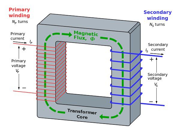
From the above figure, it is evident that few notations are common. Let us try to have a note of them. They are −
Np = Number of turns in the primary winding
Ns = Number of turns in the secondary winding
Ip = Current flowing in the primary of the transformer
Is = Current flowing in the secondary of the transformer
Vp = Voltage across the primary of the transformer
Vs = Voltage across the secondary of the transformer
Φ = Magnetic flux present around the core of the transformer.
Transformer in a Circuit
The following figure shows how a transformer is represented in a circuit. The primary winding, the secondary winding and the core of the transformer are also represented in the following figure.
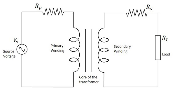
Hence, when a transformer is connected in a circuit, the input supply is given to the primary coil so that it produces varying magnetic flux with this power supply and that flux is induced into the secondary coil of the transformer, which produces the varying EMF of the varying flux. As the flux should be varying, for the transfer of EMF from primary to secondary, a transformer always works on alternating current AC.
Step-up and Step-down
Depending upon the number of turns in the secondary winding, the transformer can be called as a Step up or a Step down transformer.
The main point to be noted here is that, there will not be any difference in the primary and secondary power of the transformer. Accordingly, if the voltage is high at secondary, then low current is drawn to make the power stable. As well, if the voltage in the secondary is low, then high current is drawn so as the power must be same as the primary side.
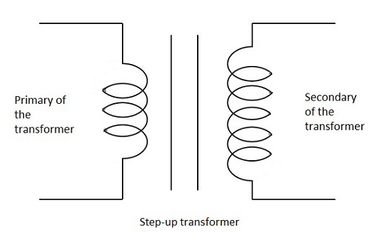
Step Up
When the secondary winding has more number of turns than the primary winding, then the transformer is said to be a Step-up transformer. Here the induced EMF is greater than the input signal.
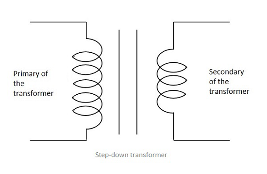
Step Down
When the secondary winding has lesser number of turns than the primary winding, then the transformer is said to be a Step-down transformer. Here the induced EMF is lesser than the input signal.
Turns Ratio
As the number of turns of primary and secondary windings affect the voltage ratings, it is important to maintain a ratio between the turns so as to have an idea regarding the voltages induced.
The ratio of number of turns in the primary coil to the number of turns in the secondary coil is called as the turns ratio or the ratio of transformation. The turns ratio is usually denoted by N.
$$N\:\:=\:\:Turns\:ratio\:\:=\:\:\frac{Number\:of\:turns\:on\:Primary}{Number\:of\:turns\:on\:Secondary}\:\:=\:\:\frac{N_{p}}{N_{s}}$$
The ratio of the primary to the secondary, the ratio of the input to the output, and the turns ratio of any given transformer will be the same as its voltage ratio. Hence this can be written as
$$\frac{N_{p}}{N_{s}}\:\:=\:\:\frac{V_{p}}{V_{s}}\:\:=\:\:N\:\:=\:\:Turns\:ratio$$
The turns ratio also states whether the transformer is a step-up or a step-down transformer. For example, a turns ratio of 1:3 states that the transformer is a step-up and the ratio 3:1 states that it is a step-down transformer.
