- Basic Electronics - Materials
- Basic Electronics - Energy Bands
- Basic Electronics - Semiconductors
- Basic Electronics - Hall Effect
- Resistors
- Basic Electronics - Resistors
- Circuit Connections in Resistors
- Non-linear Resistors
- Basic Electronics - Linear Resistors
- Basic Electronics - Fixed Resistors
- Capacitors
- Basic Electronics - Capacitors
- Circuit Connections in Capacitors
- Variable Capacitors
- Basic Electronics - Fixed Capacitors
- Polarized Capacitors
- Inductors
- Basic Electronics - Inductors
- Basic Electronics - Inductance
- Circuit Connections in Inductors
- Types of Inductors
- Basic Electronics - RF Inductors
- Transformers
- Basic Electronics - Transformers
- Types of Transformers
- Transformers based on Usage
- Transformer Efficiency
- Diodes
- Basic Electronics - Diodes
- Basic Electronics - Junction Diodes
- Special Purpose Diodes
- Optoelectronic Diodes
- Transistors
- Basic Electronics - Transistors
- Transistor Configurations
- Transistor Regions of Operation
- Transistor Load Line Analysis
- Types of Transistors
- Basic Electronics - JFET
- Basic Electronics - MOSFET
- Basic Electronics Useful Resources
- Basic Electronics - Quick Guide
- Basic Electronics - Useful Resources
- Basic Electronics - Discussion
Basic Electronics - Capacitors
A Capacitor is a passive component that has the ability to store the energy in the form of potential difference between its plates. It resists a sudden change in voltage. The charge is stored in the form of potential difference between two plates, which form to be positive and negative depending upon the direction of charge storage.
A non-conducting region is present between these two plates which is called as dielectric. This dielectric can be vacuum, air, mica, paper, ceramic, aluminum etc. The name of the capacitor is given by the dielectric used.
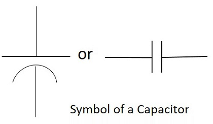
Symbol and Units
The standard units for capacitance is Farads. Generally, the values of capacitors available will be in the order of micro-farads, pico-farads and nano-farads. The symbol of a capacitor is as shown below.
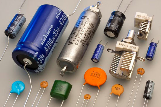
The Capacitance of a capacitor is proportional to the distance between the plates and is inversely proportional to the area of the plates. Also, the higher the permittivity of a material, the higher will be the capacitance. The permittivity of a medium describes how much electric flux is being generated per unit charge in that medium. The following image shows some practical capacitors.
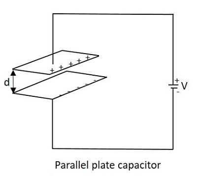
When two plates having same area A, and equal width are placed parallel to each other with a separation of distance d, and if some energy is applied to the plates, then the capacitance of that parallel plate capacitor can be termed as −
$$C\:\:=\:\:\frac{\varepsilon_{0}\:\:\varepsilon_{r}\:\:d}{A}$$
Where
C = Capacitance of a capacitor
$\varepsilon_{0}$ = permittivity of free space
$\varepsilon_{r}$ = permittivity of dielectric medium
d = distance between the plates
A = area of the two conducting plates
With some voltage applied, the charge deposits on the two parallel plates of the capacitor. This charge deposition occurs slowly and when the voltage across the capacitor equals the voltage applied, the charging stops, as the voltage entering equals the voltage leaving.
The rate of charging depends upon the value of capacitance. The greater the value of capacitance, the slower the rate of change of voltage in the plates.
Working of a Capacitor
A Capacitor can be understood as a two-terminal passive component which stores electrical energy. This electrical energy is stored in electrostatic field.
Initially, the negative and positive charges on two plates of the capacitor are in equilibrium. There is no tendency for a capacitor to get charged or discharged. The negative charge is formed by the accumulation of electrons, while the positive charge is formed by the depletion of electrons. As this happens without any external charge given, this state is electrostatic condition. The figure below shows the capacitor with static charges.
The accumulation and depletion of electrons according to the varying positive and negative cycles of the AC supply, can be understood as current flow. This is called as Displacement Current. The direction of this current flow keeps on changing as this is AC.
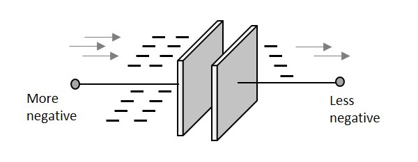
Charging of a Capacitor
When an external voltage is given, the electric charge gets converted into electrostatic charge. This happens while the capacitor is charging. The positive potential of the supply, attracts the electrons from the positive plate of the capacitor, making it more positive. While the negative potential of the supply, forces the electrons to the negative plate of the capacitor, making it more negative. The figure below explains this.
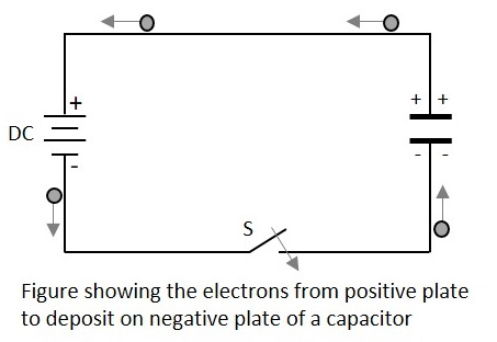
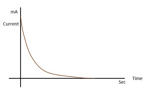
During this process of charging, the electrons move through the DC supply but not through the dielectric which is an insulator. This displacement is large, when the capacitor starts to charge but reduces as it charges. The capacitor stops charging when the voltage across capacitor equals the supply voltage.
Let us see what happens to the dielectric when the capacitor begins to charge.
Dielectric behavior
As the charges deposit on the plates of the capacitor, an electrostatic field is formed. The strength of this electrostatic field depends upon the magnitude of charge on the plate and the permittivity of the dielectric material. Permittivity is the measure of dielectric whether how far it allows the electrostatic lines to pass through it.
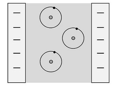
The dielectric is actually an insulator. It has electrons in the outer most orbit of the atoms. Let us observe how they get affected. When there is no charge on the plates, the electrons in the dielectric move in circular orbit. This is as shown in the figure below.
When charge deposition takes place, the electrons tend to move towards the positive charged plate, but still they keep on revolving as shown in the figure.
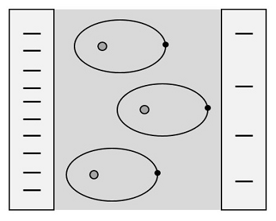
If the charge increases further, the orbits expand more. But if it still increases, the dielectric breaks down shorting the capacitor. Now, the capacitor being fully charged, its ready to get discharged. It is enough if we provide a path for them to travel from negative to positive plate. The electrons flow without any external supply as there are too many number of electrons on one side and barely any electrons on the other. This imbalance is adjusted by the discharge of the capacitor.
Also, when a discharge path is found, the atoms in the dielectric material tend to get to their normal circular orbit and hence forces the electrons to get discharged. This kind of discharge enables capacitors to deliver high currents in a short period of time, just as in a camera flash.
Color Coding
To know the value of a capacitor, it is usually labelled as below −
n35 = 0.35nF or 3n5 = 3.5nF or 35n = 35nF and so on.
Sometimes the markings will be like 100K which means, k = 1000pF. Then the value will be 100 × 1000pF = 100nF.
Though these number markings are being used now-a-days, an International color coding scheme was developed long ago, to understand the values of capacitors. The color coding indications are just as given below.
| Band colour | Digit A and B | Multiplier | Tolerance (t) > 10pf | Tolerance (t) < 10pf | Temperature coefficient |
|---|---|---|---|---|---|
| Black | 0 | × 1 | ±20% | ±2.0pF | |
| Brown | 1 | × 10 | ±1% | ±0.1pF | -33 × 10-6 |
| Red | 2 | × 100 | ±2% | ±0.25pF | -75 × 10-6 |
| Orange | 3 | × 1,000 | ±3% | -150 × 10-6 | |
| Yellow | 4 | × 10,000 | ±4% | -220 × 10-6 | |
| Green | 5 | × 100,000 | ±5% | ±0.5pF | -330 × 10-6 |
| Blue | 6 | × 1,000000 | -470 × 10-6 | ||
| Violet | 7 | -750 × 10-6 | |||
| Gray | 8 | × 0.01 | +80%, -20% | ||
| White | 9 | × 0.1 | ±10% | ±1.0pF | |
| Gold | × 0.1 | ±5% | |||
| Silver | × 0.01 | ±10% |
These indications were used to identify the value of capacitors.
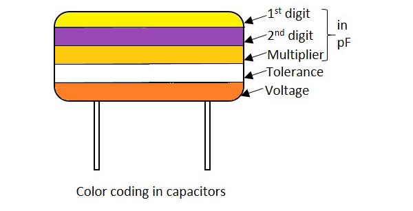
In these five band capacitors, the first two bands represent digits, third one indicates multiplier, fourth for tolerance and the fifth represents voltage. Let us look at an example to understand the color coding process.
Example 1 − Determine the value of a capacitor with a color code yellow, violet, orange, white and red.
Solution − The value of yellow is 4, violet is 7, orange is 3 which represents multiplier. White is ±10 which is the tolerance value. Red represents the voltage. But to know the voltage rating, we have got another table, from which the particular band to which this capacitor belongs, has to be known.
Hence the value of the capacitor is 47nF, 10% 250v (voltage for V band)
The following table shows how voltage is determined depending upon the bands the capacitors belong to.
| Band colour | Voltage Rating (V) | ||||
|---|---|---|---|---|---|
| TYPE J | TYPE K | TYPE L | TYPE M | TYPE N | |
| Black | 4 | 100 | 10 | 10 | |
| Brown | 6 | 200 | 100 | 1.6 | |
| Red | 10 | 300 | 250 | 4 | 35 |
| Orange | 15 | 400 | 40 | ||
| Yellow | 20 | 500 | 400 | 6.3 | 6 |
| Green | 25 | 600 | 16 | 15 | |
| Blue | 35 | 700 | 630 | 20 | |
| Violet | 50 | 800 | |||
| Gray | 900 | 25 | 25 | ||
| White | 3 | 1000 | 2.5 | 3 | |
| Gold | 2000 | ||||
| Silver | |||||
With the help of this table, the voltage rating for each band of capacitors is known according to the color given. The type of voltage ratings also indicates the type of capacitors. For example, TYPE J ones are Dipped Tantalum Capacitors, TYPE K ones are Mica Capacitors, TYPE L ones are Polystyrene Capacitors, TYPE M ones are Electrolytic Band 4 Capacitors and TYPE N ones are Electrolytic Band 3 Capacitors. These days, the color coding has been replaced by simple printing of value of the capacitors as mentioned previously.
Capacitive Reactance
This is an important term. Capacitive Reactance is the opposition offered by a capacitor to the alternating current flow, or simply AC current. A capacitor resists the change in the flow of current and hence it shows some opposition which can be termed as reactance, as the frequency of the input current should also be considered along with the resistance it offers.
Symbol: XC
In a purely capacitive circuit, the current IC leads the applied voltage by 90
Temperature Coefficient of Capacitors
The maximum change in Capacitance of a capacitor, over a specified temperature range, can be known by the temperature coefficient of a capacitor. It states that when the temperature exceeds a certain point, the change in capacitance of a capacitor that might occur is understood as the temperature coefficient of capacitors.
All the capacitors are usually manufactured considering a reference temperature of 25C. Hence the temperature coefficient of capacitors is considered for the values of temperatures that are above and below this value.
