- Basic Electronics - Materials
- Basic Electronics - Energy Bands
- Basic Electronics - Semiconductors
- Basic Electronics - Hall Effect
- Resistors
- Basic Electronics - Resistors
- Circuit Connections in Resistors
- Non-linear Resistors
- Basic Electronics - Linear Resistors
- Basic Electronics - Fixed Resistors
- Capacitors
- Basic Electronics - Capacitors
- Circuit Connections in Capacitors
- Variable Capacitors
- Basic Electronics - Fixed Capacitors
- Polarized Capacitors
- Inductors
- Basic Electronics - Inductors
- Basic Electronics - Inductance
- Circuit Connections in Inductors
- Types of Inductors
- Basic Electronics - RF Inductors
- Transformers
- Basic Electronics - Transformers
- Types of Transformers
- Transformers based on Usage
- Transformer Efficiency
- Diodes
- Basic Electronics - Diodes
- Basic Electronics - Junction Diodes
- Special Purpose Diodes
- Optoelectronic Diodes
- Transistors
- Basic Electronics - Transistors
- Transistor Configurations
- Transistor Regions of Operation
- Transistor Load Line Analysis
- Types of Transistors
- Basic Electronics - JFET
- Basic Electronics - MOSFET
- Basic Electronics Useful Resources
- Basic Electronics - Quick Guide
- Basic Electronics - Useful Resources
- Basic Electronics - Discussion
Basic Electronics - Inductance
The property of an inductor to get the voltage induced by the change of current flow, is defined as Inductance. Inductance is the ratio of voltage to the rate of change of current.
The rate of change of current produces change in the magnetic field, which induces an EMF in opposite direction to the voltage source. This property of induction of EMF is called as the Inductance.
The formula for inductance is
$$Inductance\:\:=\:\:\frac{volatge}{rate\:of\:change\:of\:current}$$
Units −
The unit of Inductance is Henry. It is indicated by L.
The inductors are mostly available in mH (milli Henry) and μH (micro Henry).
A coil is said to have an inductance of one Henry when an EMF of one volt is self-induced in the coil where the current flowing changed at a rate of one ampere per second.
Self-Inductance
If a coil is considered in which some current flows, it has some magnetic field, perpendicular to the current flow. When this current keeps on varying, the magnetic field also changes and this changing magnetic field, induces an EMF, opposite to the source voltage. This opposing EMF produced is the self-induced voltage and this method is called as self-inductance.
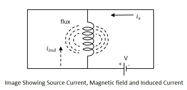
The current is in the figure indicate the source current while iind indicates the induced current. The flux represents the magnetic flux created around the coil. With the application of voltage, the current is flows and flux gets created. When the current is varies, the flux gets varied producing iind.
This induced EMF across the coil is proportional to the rate of change in current. The higher the rate of change in current the higher the value of EMF induced.
We can write the above equation as
$$E\:\:\alpha\:\:\frac{dI}{dt}$$
$$E\:\:=\:\:L\:\:\frac{dI}{dt}$$
Where,
E is the EMF produced
dI/dt indicates the rate of change of current
L indicates the co-efficient of inductance.
Self-inductance or Co-efficient of Self-inductance can be termed as
$$L\:\:=\:\:\frac{E}{\frac{dI}{dt}}$$
The actual equation is written as
$$E\:\:=\:\:-L\:\:\frac{dI}{dt}$$
The minus in the above equation indicates that the EMF is induced in opposite direction to the voltage source according to Lenzs law.
Mutual Inductance
As the current carrying coil produces some magnetic field around it, if another coil is brought near this coil, such that it is in the magnetic flux region of the primary, then the varying magnetic flux induces an EMF in the second coil. If this first coil is called as Primary coil, the second one can be called as a Secondary coil.
When the EMF is induced in the secondary coil due to the varying magnetic field of the primary coil, then such phenomenon is called as the Mutual Inductance.
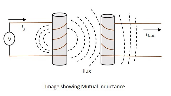
The current is in the figure indicate the source current while iind indicates the induced current. The flux represents the magnetic flux created around the coil. This spreads to the secondary coil also.
With the application of voltage, the current is flows and flux gets created. When the current is varies, the flux gets varied producing iind in the secondary coil, due to the Mutual inductance property.
The change took place like this.
$$V_{p}\:\:I_{p}\rightarrow\:\:B\:\:\rightarrow\:\:V_{s}\:\:I_{s}$$
Where,
Vp ip Indicate the Voltage and current in Primary coil respectively
B Indicates Magnetic flux
Vs is Indicate the Voltage and current in Secondary coil respectively
Mutual inductance M of the two circuits describes the amount of the voltage in the secondary induced by the changes in the current of the primary.
$$V(Secondary)\:\:=\:\:-M\frac{\Delta I}{\Delta t}$$
Where $\frac{\Delta I}{\Delta t}$ the rate of change of current with time and M is the co-efficient of Mutual inductance. The minus sign indicates the direction of current being opposite to the source.
Units −
The units of Mutual inductance is
$$volt\:\:=\:\:M\frac{amps}{sec}$$
(From the above equation)
$$M\:\:=\:\:\frac{volt.\:sec}{amp}$$
$$=\:\:Henry(H)$$
Depending upon the number of turns of the primary and the secondary coils, the magnetic flux linkage and the amount of induced EMF varies. The number of turns in primary is denoted by N1 and secondary by N2. The co-efficient of coupling is the term that specifies the mutual inductance of the two coils.
Factors affecting Inductance
There are a few factors that affect the performance of an inductor. The major ones are discussed below.
Length of the coil
The length of the inductor coil is inversely proportional to the inductance of the coil. If the length of the coil is more, the inductance offered by that inductor gets less and vice versa.
Cross sectional area of the coil
The cross sectional area of the coil is directly proportional to the inductance of the coil. The higher the area of the coil, the higher the inductance will be.
Number of turns
With the number of turns, the coil affects the inductance directly. The value of inductance gets square to the number of turns the coil has. Hence the higher the number of turns, square of it will be the value of inductance of the coil.
Permeability of the core
The permeability (μ) of the core material of inductor indicates the support the core provides for the formation of a magnetic field within itself. The higher the permeability of the core material, the higher will be the inductance.
Coefficient of Coupling
This is an important factor to be known for calculating Mutual inductance of two coils. Let us consider two nearby coils of N1 and N2 turns respectively.
The current through first coil i1 produces some flux Ψ1. The amount of magnetic flux linkages is understood by weber-turns.
Let the amount of magnetic flux linkage to the second coil, due to unit current of i1 be
$$\frac{N_{2}\varphi_{1}}{i_{1}}$$
This can be understood as the Co-efficient of Mutual inductance, which means
$$M\:\:=\:\:\frac{N_{2}\varphi_{1}}{i_{1}}$$
Hence the Co-efficient of Mutual inductance between two coils or circuits is understood as the weber-turns in one coil due to 1A of current in the other coil.
If the self-inductance of first coil is L1, then
$$L_{1}i_{1}\:\:=\:\:{N_{1}\varphi_{1}}\:\:=>\:\:\frac{L_{1}}{N_{1}}\:\:\frac{\varphi_{1}}{i_{1}}$$
$$M\:\:=\:\:\frac{N_{2}L_{1}}{N_{1}}$$
Similarly, coefficient of mutual inductance due to current i2 in the second coil is
$$M\:\:=\:\:\frac{N_{1}\varphi_{2}}{i_{2}}\:\dotsm\:\dotsm\:\dotsm\:\dotsm\:\:1$$
If self-inductance of second coil is L2
$$L_{2}i_{2}\:\:=\:\:N_{2}\varphi_{2}$$
$$\frac{L_{2}}{N_{2}}\:\:=\:\:\frac{\varphi_{2}}{i_{2}}$$
Therefore,
$$M\:\:=\:\:\frac{N_{1}L_{2}}{N_{2}}\:\dotsm\:\dotsm\:\dotsm\:\dotsm\:\:2$$
Multiplying 1 and 2, we get
$$M\:\:\times\:\:M=\:\:\frac{N_{2}L_{1}}{N_{1}}\:\:\times\:\:\frac{N_{1}L_{2}}{N_{2}}$$
$$M^{2}\:\:=\:\:L_{1}L_{2}\:\:=>\:\:M\:\:=\:\:\sqrt{L_{1}L_{2}}$$
The above equation holds true when the whole changing flux of primary coil links with the secondary coil, which is an ideal case. But in practice, it is not the case. Hence, we can write as
$$M\:\:\neq\:\:\sqrt{L_{1}L_{2}}$$
$$and \frac{M}{\sqrt{L_{1}L_{2}}}\:\:=\:\:K\:\:\neq\:\:1$$
Where K is known as the coefficient of coupling.
The Coefficient of coupling K can be defined as the ratio of actual coefficient of mutual inductance to the ideal (maximum) coefficient of mutual inductance.
If the value of k is near to unity, then the coils are said to be tightly coupled and if the value of k = 0, then the coils are said to be loosely coupled.
Applications of Inductors
There are many applications of Inductors, such as −
Inductors are used in filter circuits to sense high-frequency components and suppress noise signals
To isolate the circuit from unwanted HF signals.
Inductors are used in electrical circuits to form a transformer and isolate the circuits from spikes.
Inductors are also used in motors.
