- Basic Electronics - Materials
- Basic Electronics - Energy Bands
- Basic Electronics - Semiconductors
- Basic Electronics - Hall Effect
- Resistors
- Basic Electronics - Resistors
- Circuit Connections in Resistors
- Non-linear Resistors
- Basic Electronics - Linear Resistors
- Basic Electronics - Fixed Resistors
- Capacitors
- Basic Electronics - Capacitors
- Circuit Connections in Capacitors
- Variable Capacitors
- Basic Electronics - Fixed Capacitors
- Polarized Capacitors
- Inductors
- Basic Electronics - Inductors
- Basic Electronics - Inductance
- Circuit Connections in Inductors
- Types of Inductors
- Basic Electronics - RF Inductors
- Transformers
- Basic Electronics - Transformers
- Types of Transformers
- Transformers based on Usage
- Transformer Efficiency
- Diodes
- Basic Electronics - Diodes
- Basic Electronics - Junction Diodes
- Special Purpose Diodes
- Optoelectronic Diodes
- Transistors
- Basic Electronics - Transistors
- Transistor Configurations
- Transistor Regions of Operation
- Transistor Load Line Analysis
- Types of Transistors
- Basic Electronics - JFET
- Basic Electronics - MOSFET
- Basic Electronics Useful Resources
- Basic Electronics - Quick Guide
- Basic Electronics - Useful Resources
- Basic Electronics - Discussion
Circuit Connections in Inductors
An Inductor when connected in a circuit, that connection can be either series or parallel. Let us now know what will happen to the total current, voltage and resistance values if they are connected in series as well, when connected in parallel.
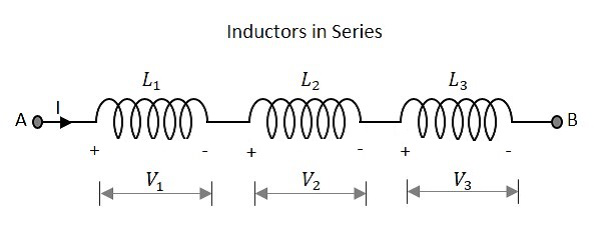
Inductors in Series
Let us observe what happens, when few inductors are connected in Series. Let us consider three resistors with different values, as shown in the figure below.
Inductance
The total inductance of a circuit having series inductors is equal to the sum of the individual inductances. Total inductance value of the network given above is
$$L_{T}\:\:=\:\:L_{1}\:\:+\:\:L_{2}\:\:+\:\:L_{3}$$
Where L1 is the inductance of 1st resistor, L2 is the inductance of 2nd resistor and L3 is the inductance of 3rd resistor in the above network.
Voltage
The total voltage that appears across a series inductors network is the addition of voltage drops at each individual inductances.
Total voltage that appears across the circuit
$$V\:\:=\:\:V_{1}\:\:+\:\:V_{2}\:\:+\:\:V_{3}$$
Where V1 is the voltage drop across 1st inductor, V2 is the voltage drop across 2nd inductor and V3 is the voltage drop across 3rd inductor in the above network.
Current
The total amount of Current that flows through a set of inductors connected in series is the same at all the points throughout the network.
The Current through the network
$$I\:\:=\:\:I_{1}\:\:=\:\:I_{2}\:\:=\:\:I_{3}$$
Where I1 is the current through the 1st inductor, I2 is the current through the 2nd inductor and I3 is the current through the 3rd inductor in the above network.
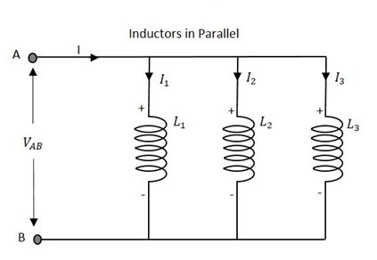
Inductors in Parallel
Let us observe what happens, when few resistors are connected in Parallel. Let us consider three resistors with different values, as shown in the figure below.
Inductance
The total inductance of a circuit having Parallel resistors is calculated differently from the series inductor network method. Here, the reciprocal (1/R) value of individual inductances are added with the inverse of algebraic sum to get the total inductance value.
Total inductance value of the network is
$$\frac{1}{L_{T}}\:\:=\:\:\frac{1}{L_{1}}\:\:+\:\:\frac{1}{L_{2}}\:\:+\:\:\frac{1}{L_{3}}$$
Where L1 is the inductance of 1st inductor, L2 is the inductance of 2nd inductor and L3 is the inductance of 3rd inductor in the above network.
From the method we have for calculating parallel inductance, we can derive a simple equation for two-inductor parallel network. It is
$$L_{T}\:\:=\:\:\frac{L_{1}\:\:\times\:\: L_{2}}{L_{1}\:\:+\:\: L_{2}}$$
Voltage
The total voltage that appears across a Parallel inductors network is same as the voltage drops at each individual inductances.
The Voltage that appears across the circuit
$$V\:\:=\:\:V_{1}\:\:=\:\:V_{2}\:\:=\:\:V_{3}$$
Where V1 is the voltage drop across 1st inductor, V2 is the voltage drop across 2nd inductor and V3 is the voltage drop across 3rd inductor in the above network. Hence the voltage is same at all the points of a parallel inductor network.
Current
The total amount of current entering a Parallel inductive network is the sum of all individual currents flowing in all the Parallel branches. The inductance value of each branch determines the value of current that flows through it.
The total Current through the network is
$$I\:\:=\:\:I_{1}\:\:+\:\:I_{2}\:\:+\:\:I_{3}$$
Where I1 is the current through the 1st inductor, I2 is the current through the 2nd inductor and I3 is the current through the 3rd inductor in the above network.
Hence the sum of individual currents in different branches obtain the total current in a parallel network.
Inductive Reactance
Inductive Reactance is the opposition offered by an inductor to the alternating current flow, or simply AC current. An inductor has the property of resisting the change in the flow of current and hence it shows some opposition which can be termed as reactance, as the frequency of the input current should also be considered along with the resistance it offers.
Indication − XL
Units − Ohms
Symbol − Ω
In a purely inductive circuit, the current IL lags the applied voltage by 90. Inductive reactance is calculated by,
$$X_{L}\:\:=\:\:2\pi fL$$
Where f is the frequency of the signal. Hence inductive reactance is a function of frequency and inductance.
