- Basic Electronics - Materials
- Basic Electronics - Energy Bands
- Basic Electronics - Semiconductors
- Basic Electronics - Hall Effect
- Resistors
- Basic Electronics - Resistors
- Circuit Connections in Resistors
- Non-linear Resistors
- Basic Electronics - Linear Resistors
- Basic Electronics - Fixed Resistors
- Capacitors
- Basic Electronics - Capacitors
- Circuit Connections in Capacitors
- Variable Capacitors
- Basic Electronics - Fixed Capacitors
- Polarized Capacitors
- Inductors
- Basic Electronics - Inductors
- Basic Electronics - Inductance
- Circuit Connections in Inductors
- Types of Inductors
- Basic Electronics - RF Inductors
- Transformers
- Basic Electronics - Transformers
- Types of Transformers
- Transformers based on Usage
- Transformer Efficiency
- Diodes
- Basic Electronics - Diodes
- Basic Electronics - Junction Diodes
- Special Purpose Diodes
- Optoelectronic Diodes
- Transistors
- Basic Electronics - Transistors
- Transistor Configurations
- Transistor Regions of Operation
- Transistor Load Line Analysis
- Types of Transistors
- Basic Electronics - JFET
- Basic Electronics - MOSFET
- Basic Electronics Useful Resources
- Basic Electronics - Quick Guide
- Basic Electronics - Useful Resources
- Basic Electronics - Discussion
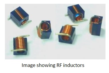
Basic Electronics - RF Inductors
RF inductors are the radio frequency inductors, which are used at high resonant frequencies. These can be multilayered coil inductor or a thin film coated ceramic inductor or some wire wound ceramic inductor. The following figure represents few RF inductors.
These inductors are characterized by low current rating and high electrical resistance. But as the high frequencies are used here, the wire resistance increases. Also, few effects come into picture because of these high resonant radio frequencies. Let us have a look at them.
Skin Effect
At high frequencies, the alternating current has a tendency of unequal distribution of current through the conductor. The electric current flows highly at the surface of the conductor than at its center. It gets its energy concentrated in the skin of the conductor, leaving the deep core of the conductor, as shown in the following figure.
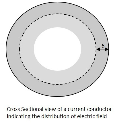
As the energy gets concentrated at the skin of the conductor, this effect is called as the Skin Effect. Actually this skin effect is caused due to the eddy currents which are produced by the changing Magnetic field, resulting from alternating current. Now-a-days, the conductors carrying higher frequencies are made in the form of tube shape, in order to reduce the weight and cost of the conductors.
Proximity Effect
Along with the above one, this is another effect, which is observed here. Proximity effect is the one which increases the resistance of the wire at high frequencies. Proximity is the word which says that the effect will be on adjacent wires. The following figure shows the concentration of current on the edges of the adjacent cables.
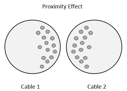
Each turn has some magnetic field which induces eddy currents in the wire that causes the current to be focused on the side of the adjacent wire. With this effect, the effective cross sectional area of the wire gets reduced and its resistance gets increased.
Parasitic Capacitance
Usually, an inductor internally contains a resistor in series (wire resistance) and a capacitor in shunt (parasitic capacitance). Each turn of winding has slightly different potential, in an inductor. The following figure shows the capacitance effect in an inductor.
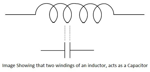
The two conductors that present in each turn, act as capacitor plates with air as dielectric. A capacitance called as Parasitic Capacitance exists here. In order to avoid this in certain applications, the windings are made far to each other.
As the frequency increases, the impedance of the parasitic capacitance decreases and the impedance of inductor increases. Hence the inductor tends to behave like a capacitor.
Dielectric losses
The current through the conductor of an inductor makes the molecules of the insulators exert energy in the form of heat. The higher the frequency, the greater the heat dissipation will be.
Chokes
Inductors are also called as chokes. An Inductor blocks AC components and sends DC components through it. Hence as it chokes or stops AC, an inductor can simply be termed as a Choke.
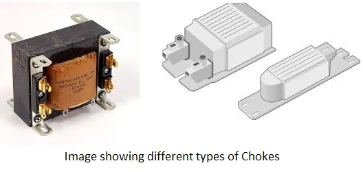
A coil of insulated wire is often wound on a magnetic core to form a choke. As the signal frequency increases, the impedance of the choke increases. Due to its reactance, it can limit the amount AC through it. Even though, practically some amount of AC passes through it due to its low electrical resistance. These are mostly used in tube lights and in transformers in electronic applications.
