- Basic Electronics - Materials
- Basic Electronics - Energy Bands
- Basic Electronics - Semiconductors
- Basic Electronics - Hall Effect
- Resistors
- Basic Electronics - Resistors
- Circuit Connections in Resistors
- Non-linear Resistors
- Basic Electronics - Linear Resistors
- Basic Electronics - Fixed Resistors
- Capacitors
- Basic Electronics - Capacitors
- Circuit Connections in Capacitors
- Variable Capacitors
- Basic Electronics - Fixed Capacitors
- Polarized Capacitors
- Inductors
- Basic Electronics - Inductors
- Basic Electronics - Inductance
- Circuit Connections in Inductors
- Types of Inductors
- Basic Electronics - RF Inductors
- Transformers
- Basic Electronics - Transformers
- Types of Transformers
- Transformers based on Usage
- Transformer Efficiency
- Diodes
- Basic Electronics - Diodes
- Basic Electronics - Junction Diodes
- Special Purpose Diodes
- Optoelectronic Diodes
- Transistors
- Basic Electronics - Transistors
- Transistor Configurations
- Transistor Regions of Operation
- Transistor Load Line Analysis
- Types of Transistors
- Basic Electronics - JFET
- Basic Electronics - MOSFET
- Basic Electronics Useful Resources
- Basic Electronics - Quick Guide
- Basic Electronics - Useful Resources
- Basic Electronics - Discussion
Circuit Connections in Resistors
A Resistor when connected in a circuit, that connection can be either series or parallel. Let us now know what will happen to the total current, voltage and resistance values if they are connected in series as well, when connected in parallel.
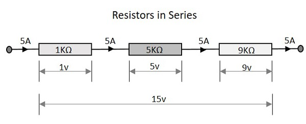
Resistors in Series
Let us observe what happens, when few resistors are connected in Series. Let us consider three resistors with different values, as shown in the figure below.
Resistance
The total resistance of a circuit having series resistors is equal to the sum of the individual resistances. That means, in the above figure there are three resistors having the values 1KΩ, 5KΩ and 9KΩ respectively.
Total resistance value of the resistor network is −
$$R\:\:=\:\:R_{1}\:+\:R_{2}\:+\:R_{3}$$
Which means 1 + 5 + 9 = 15KΩ is the total resistance.
Where R1 is the resistance of 1st resistor, R2 is the resistance of 2nd resistor and R3 is the resistance of 3rd resistor in the above resistor network.
Voltage
The total voltage that appears across a series resistors network is the addition of voltage drops at each individual resistances. In the above figure we have three different resistors which have three different values of voltage drops at each stage.
Total voltage that appears across the circuit −
$$V\:\:=\:\:V_{1}\:+\:V_{2}\:+\:V_{3}$$
Which means 1v + 5v + 9v = 15v is the total voltage.
Where V1 is the voltage drop of 1st resistor, V2 is the voltage drop of 2nd resistor and V3 is the voltage drop of 3rd resistor in the above resistor network.
Current
The total amount of Current that flows through a set of resistors connected in series is the same at all the points throughout the resistor network. Hence the current is same 5A when measured at the input or at any point between the resistors or even at the output.
Current through the network −
$$I\:\:=\:\:I_{1}\:=\:I_{2}\:=\:I_{3}$$
Which means that current at all points is 5A.
Where I1 is the current through the 1st resistor, I2 is the current through the 2nd resistor and I3 is the current through the 3rd resistor in the above resistor network.
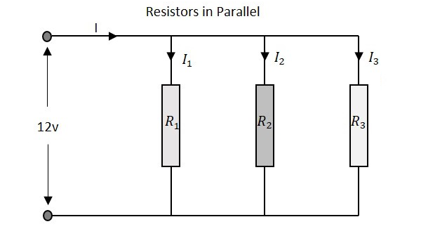
Resistors in Parallel
Let us observe what happens, when few resistors are connected in Parallel. Let us consider three resistors with different values, as shown in the figure below.
Resistance
The total resistance of a circuit having Parallel resistors is calculated differently from the series resistor network method. Here, the reciprocal (1/R) value of individual resistances are added with the inverse of algebraic sum to get the total resistance value.
Total resistance value of the resistor network is −
$$\frac{1}{R}\:\:=\:\:\frac{1}{R_{1}}\:\:+\:\:\frac{1}{R_{2}}\:\:+\frac{1}{R_{3}}$$
Where R1 is the resistance of 1st resistor, R2 is the resistance of 2nd resistor and R3 is the resistance of 3rd resistor in the above resistor network.
For example, if the resistance values of previous example are considered, which means R1 = 1KΩ, R2 = 5KΩ and R3 = 9KΩ. The total resistance of parallel resistor network will be −
$$\frac{1}{R}\:\:=\:\:\frac{1}{1}\:\:+\:\:\frac{1}{5}\:\:+\frac{1}{9}$$
$$=\:\:\frac{45\:\:+\:\:9\:\:+\:\:5}{45}\:\:=\:\:\frac{59}{45}$$
$$R\:\:=\:\:\frac{45}{59}\:\:=\:\:0.762K\Omega\:\:=\:\:76.2\Omega$$
From the method we have for calculating parallel resistance, we can derive a simple equation for two-resistor parallel network. It is −
$$R\:\:=\:\:\frac{R_{1}\:\:\times\:\:R_{2}}{R_{1}\:\:+\:\:R_{2}}\:$$
Voltage
The total voltage that appears across a Parallel resistors network is same as the voltage drops at each individual resistance.
The Voltage that appears across the circuit −
$$V\:\:=\:\:V_{1}\:=\:V_{2}\:=\:V_{3}$$
Where V1 is the voltage drop of 1st resistor, V2 is the voltage drop of 2nd resistor and V3 is the voltage drop of 3rd resistor in the above resistor network. Hence the voltage is same at all the points of a parallel resistor network.
Current
The total amount of current entering a Parallel resistive network is the sum of all individual currents flowing in all the Parallel branches. The resistance value of each branch determines the value of current that flows through it. The total current through the network is
$$I\:\:=\:\:I_{1}\:+\:I_{2}\:+\:I_{3}$$
Where I1 is the current through the 1st resistor, I2 is the current through the 2nd resistor and I3 is the current through the 3rd resistor in the above resistor network. Hence the sum of individual currents in different branches obtain the total current in a parallel resistive network.
A Resistor is particularly used as a load in the output of many circuits. If at all the resistive load is not used, a resistor is placed before a load. Resistor is usually a basic component in any circuit.
