- Power Electronics - Home
- Power Electronics - Introduction
- Power Electronics - Switching Devices
- Linear Circuit Elements
- Power Electronics - Resistor
- Power Electronics - Inductor
- Power Electronics - Power Diode
- Power Diode - Reverse Recovery Characteristics
- Power Electronics - BJT
- Power Electronics - IGBT
- Power Electronics - MOSFET
- Silicon Controlled Rectifier
- SCR - Switching Characteristics
- Power Electronics - TRIAC
- Power Electronics - GTO Thyristor
- Comparision of Power Semiconductor Devices
- Thyristor - Diode Model
- Thyristor - Two Transistor Model
- Thyristor - Turn ON Methods
- Thyristor - Specifications and Ratings
- Solved Example
- Phase Controlled Converters
- Power Electronics - Pulse Converters
- Effect of Source Inductance
- Performance Parameters
- Reactive Power Control of Converters
- Power Electronics - Dual Converters
- Solved Example
- DC to DC Converters
- Power Electronics - Choppers
- Power Electronics - Control Methods
- Resonant Switching
- DC Converters Solved Example
- AC to DC Converters
- Single Phase AC Voltage Controllers
- Power Electronics - Cycloconverters
- Integral Cycle Control
- Power Electronics - Matrix Converters
- Solved Example
- Power Electronics Resources
- Power Electronics - Quick Guide
- Power Electronics - Useful Resources
- Power Electronics - Discussion
Power Electronics - TRIAC
The word TRIAC is derived from combination of capital letters TRIode and AC. It is a low power semi-conductor device acting as a switch. TRIAC is a bipolar blocking and bi-directional conducting device. It is a pulse triggered switch.
A SCR is a unidirectional device as it can conduct from anode to cathode. It has reverse blocking characteristics and current cannot flow from cathode to anode direction. But in some application, particularly in AC circuit, the bidirectional current flow is required. For this two thyristors can be integrated into a single chip as this device is called a TRIAC(triode ac switch).
TRIAC can conduct in both directions. Hence, TRIAC is a bi-directional thyristor and it is extensively used for AC controller circuits.
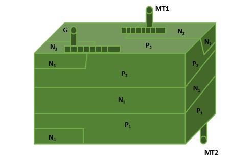
Construction of TRIAC
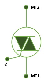
TRIAC has three terminals usually designated as MT1(main terminal 1), MT2(main terminal 2) and the gate by G as in a thyristor. The gate G is near terminal MT1.
The cross-hatched strip shows that G is connected to N3 as well as P2. Similarly, terminal MT1 is connected to P2 and N2, terminal MT2 to P1 and N4.
With no signal to gate, the triac will block both half cycles of the ac applied voltage in case peak value of this voltage is less than the break-over voltage of VBO1 or VBO2 of the triac. The triac can, however, be turned on in each half cycle of the applied voltage by applying a positive or negative voltage to the gate with respect to terminal MT1.
Modes Of Operations
TRIAC under go four modes of operations −
- MT2 is positive and gate current is also positive
- MT2 is positive but gate current is negative
- MT1 is positive and gate current is also positive
- MT1 is positive but gate current is negative
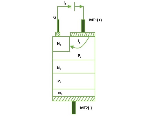
MT2 is positive and gate current is also positive
When MT2 is positive with respect to MT1, junction P1N1, P2N2 are forward biased but junction N1P2 is reverse biased. When gate terminal is positive with respect to MT1, gate current flows mainly through P2N2 junction.
When gate current has injected sufficient charge into P2 layer, reverse biased junction N1P2 breaks down just as in normal SCR. As a result, triac starts conducting through P1N1P2N2 layers. Under this condition, triac operates in first quadrant.
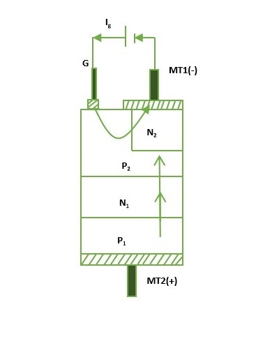
MT2 is positive but gate current is negative
when gate terminal is negative with respect to MT1, gate current flows through P2N3 junction, and reverse biased junction N1P2 is forward biased as in a normal thyristor. As a result, triac starts conducting through P1N1P2N3 layers initially.
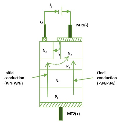
With the conduction of P1 N1 P2 N3, the voltage drop across this path falls but potential of layer between P2 N3 raises towards anode potential of MT2.
MT1 is positive and gate current is also positive
The gate current Ig forward biases P2 N2 junction. Layer N2 injects electrons into P2 layer. As a result junction N1 P1 breaks down as in a conventional thyristor.
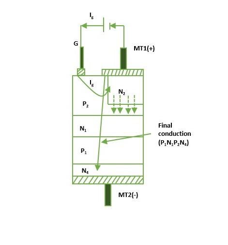
Eventually the structure P2 N1 P1 N4 is completely turned on. As usual, the current after turn-on is limited by the external load. As the triac is turned on by remote gate N2, the device is less sensitive in the third quadrant with positive gate current.
MT1 is positive but gate current is negative
In this mode, N3 acts as a remote gate. The gate current Igflows from P2 to N3 as in a normal thyristor. Reverse-biased junction N1 P1 is broken and finally, the structure P2 N1 P1 N4 is turned on completely.
From the above discussion, we can conclude −
- Sensitivity of the triac is greatest in the first quadrant when turned on with positive gate current and also in the third quadrant when turned on with negative gate current
- Sensitivity of the triac is low in the first quadrant when turned on with negative gate current and also in the third quadrant when turned-on with positive gate current
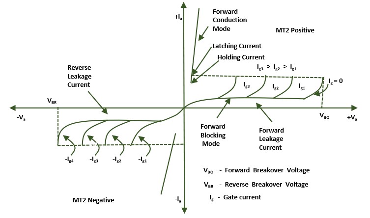
Following are the static V - I characteristics of TRIAC
Typical Ratings
Following are typical rating of the TRIAC −
- Voltage(V) = 1200 volts
- Current(I) = 300 amperes
- Frequency(f) = 500Hz
