- Power Electronics - Home
- Power Electronics - Introduction
- Power Electronics - Switching Devices
- Linear Circuit Elements
- Power Electronics - Resistor
- Power Electronics - Inductor
- Power Electronics - Power Diode
- Power Diode - Reverse Recovery Characteristics
- Power Electronics - BJT
- Power Electronics - IGBT
- Power Electronics - MOSFET
- Silicon Controlled Rectifier
- SCR - Switching Characteristics
- Power Electronics - TRIAC
- Power Electronics - GTO Thyristor
- Comparision of Power Semiconductor Devices
- Thyristor - Diode Model
- Thyristor - Two Transistor Model
- Thyristor - Turn ON Methods
- Thyristor - Specifications and Ratings
- Solved Example
- Phase Controlled Converters
- Power Electronics - Pulse Converters
- Effect of Source Inductance
- Performance Parameters
- Reactive Power Control of Converters
- Power Electronics - Dual Converters
- Solved Example
- DC to DC Converters
- Power Electronics - Choppers
- Power Electronics - Control Methods
- Resonant Switching
- DC Converters Solved Example
- AC to DC Converters
- Single Phase AC Voltage Controllers
- Power Electronics - Cycloconverters
- Integral Cycle Control
- Power Electronics - Matrix Converters
- Solved Example
- Power Electronics Resources
- Power Electronics - Quick Guide
- Power Electronics - Useful Resources
- Power Electronics - Discussion
Power Electronics - Integral Cycle Control
Integral cycle controllers are converters with the ability to perform direct switching without losses. The process directly converts AC to AC without having to perform the intermediate processes of AC to DC then DC to AC.
The basic integral control cycle is sinusoidal in nature. It operates by combining and eliminating higher frequency half cycles from AC input. The controllers are normally, turned ON of OFF during half cycles where the voltage input is at zero since only the full or half cycles are utilized. Therefore, integral cycle circuits achieve switching at zero voltage without requiring a resonant circuit.
The diagram below shows a simple integral cycle controller. It contains a load and a power switch, which performs the direct conversion. This diagram shows the conversion of source frequency from a factor of three to one.
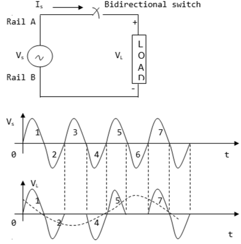
Power Factor Control
Power factor control, also known as correction of power factor, is the process of reducing the amount of reactive power. The power electronic device used in this case is called a power factor controller (PFC). From the power triangle (which comprises reactive, true and apparent power), the reactive power is at right angle (90°) to the true power and is used to energize the magnetic field. Although reactive power does not have a real value in electronic equipment, the bill for electricity comprises real and reactive power costs. This makes it necessary to have power factor controllers in electronic devices.
Power factor (k) is defined as the ratio of the real power (in kW) to the reactive power (in kVAr). Its value ranges from 0 to 1. If a device has a power factor of 0.8 and above, it is said to be using power efficiently. Incorporating a PFC ensures the power factor ranges from 0.95 to 0.99. Power factor controllers are mainly in industrial equipment to minimize reactive power generated by fluorescent lighting and electric motors.
To ensure power factor is improved without causing harmonic distortion, the conventional capacitors should not be used. Instead, filters (combination of capacitors and reactors) for harmonic suppression are used. The figure below shows a harmonic filter.
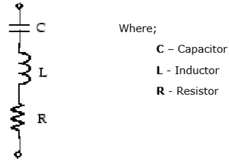
The above type of harmonic filter is referred to as a single tuned filter. A quality factor Q of this filter is defined as quality factor of its reactance (XL) at Q (tuning frequency) where Q is given by (nXL/R).
