- Power Electronics - Home
- Power Electronics - Introduction
- Power Electronics - Switching Devices
- Linear Circuit Elements
- Power Electronics - Resistor
- Power Electronics - Inductor
- Power Electronics - Power Diode
- Power Diode - Reverse Recovery Characteristics
- Power Electronics - BJT
- Power Electronics - IGBT
- Power Electronics - MOSFET
- Silicon Controlled Rectifier
- SCR - Switching Characteristics
- Power Electronics - TRIAC
- Power Electronics - GTO Thyristor
- Comparision of Power Semiconductor Devices
- Thyristor - Diode Model
- Thyristor - Two Transistor Model
- Thyristor - Turn ON Methods
- Thyristor - Specifications and Ratings
- Solved Example
- Phase Controlled Converters
- Power Electronics - Pulse Converters
- Effect of Source Inductance
- Performance Parameters
- Reactive Power Control of Converters
- Power Electronics - Dual Converters
- Solved Example
- DC to DC Converters
- Power Electronics - Choppers
- Power Electronics - Control Methods
- Resonant Switching
- DC Converters Solved Example
- AC to DC Converters
- Single Phase AC Voltage Controllers
- Power Electronics - Cycloconverters
- Integral Cycle Control
- Power Electronics - Matrix Converters
- Solved Example
- Power Electronics Resources
- Power Electronics - Quick Guide
- Power Electronics - Useful Resources
- Power Electronics - Discussion
Power Electronics - Pulse Width Modulation
PWM is a technique that is used to reduce the overall harmonic distortion (THD) in a load current. It uses a pulse wave in rectangular/square form that results in a variable average waveform value f(t), after its pulse width has been modulated. The time period for modulation is given by T. Therefore, waveform average value is given by
$$\bar{y}=\frac{1}{T}\int_{0}^{T}f\left ( t \right )dt$$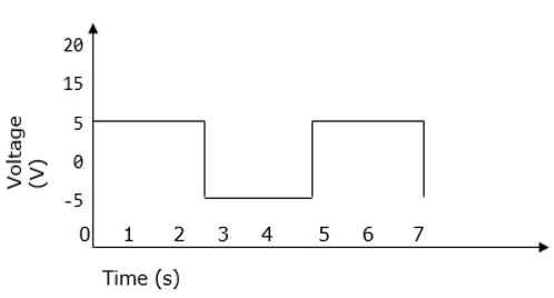
Sinusoidal Pulse Width Modulation
In a simple source voltage inverter, the switches can be turned ON and OFF as needed. During each cycle, the switch is turned on or off once. This results in a square waveform. However, if the switch is turned on for a number of times, a harmonic profile that is improved waveform is obtained.
The sinusoidal PWM waveform is obtained by comparing the desired modulated waveform with a triangular waveform of high frequency. Regardless of whether the voltage of the signal is smaller or larger than that of the carrier waveform, the resulting output voltage of the DC bus is either negative or positive.
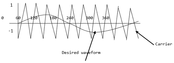
The sinusoidal amplitude is given as Am and that of the carrier triangle is give as Ac. For sinusoidal PWM, the modulating index m is given by Am/Ac.
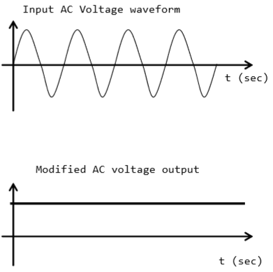
Modified Sinusoidal Waveform PWM
A modified sinusoidal PWM waveform is used for power control and optimization of the power factor. The main concept is to shift current delayed on the grid to the voltage grid by modifying the PWM converter. Consequently, there is an improvement in the efficiency of power as well as optimization in power factor.
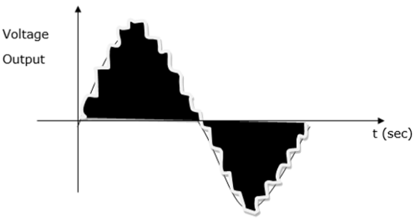
Multiple PWM
The multiple PWM has numerous outputs that are not the same in value but the time period over which they are produced is constant for all outputs. Inverters with PWM are able to operate at high voltage output.
The waveform below is a sinusoidal wave produced by a multiple PWM
Voltage and Harmonic Control
A periodic waveform that has frequency, which is a multiple integral of the fundamental power with frequency of 60Hz is known as a harmonic. Total harmonic distortion (THD) on the other hand refers to the total contribution of all the harmonic current frequencies.
Harmonics are characterized by the pulse that represent the number of rectifiers used in a given circuit. It is calculated as follows −
$$h=\left ( n\times P \right )+1 \quad or \quad -1$$Where n − is an integer 1, 2, 3, 4.n
P − Number of rectifiers
It is summarized in the table below −
Harmonic |
Frequency |
| 1st | 60 Hz |
| 2nd | 120 Hz |
| 3rd | 180Hz |
| 4th | 240Hz |
|
5th . . 49th |
300Hz . . 2940Hz |
Harmonics have an impact on the voltage and current output and can be reduced using isolation transformers, line reactors, redesign of power systems and harmonic filters.
Series Resonant Inverter
A resonant inverter is an electrical inverter whose operation is based on oscillation of resonant current. Here, the switching device and the resonanting component are connected in series to each other. As a result of the natural features of the circuit, the current passing through the switching device drops to zero.
This type of inverter yields a sinusoidal waveform at very high frequencies in the range of 20kHz-100kHz. It is therefore, most suitable for applications that demand a fixed output such as induction heating and flourescent lighting. It is usually small in size because its switching frequency is high.
A resonant inverter has numerous configurations and thus it is categorized into two groups −
- Those with unidirectional switches
- Those with bidirectional switches
