- Power Electronics - Home
- Power Electronics - Introduction
- Power Electronics - Switching Devices
- Linear Circuit Elements
- Power Electronics - Resistor
- Power Electronics - Inductor
- Power Electronics - Power Diode
- Power Diode - Reverse Recovery Characteristics
- Power Electronics - BJT
- Power Electronics - IGBT
- Power Electronics - MOSFET
- Silicon Controlled Rectifier
- SCR - Switching Characteristics
- Power Electronics - TRIAC
- Power Electronics - GTO Thyristor
- Comparision of Power Semiconductor Devices
- Thyristor - Diode Model
- Thyristor - Two Transistor Model
- Thyristor - Turn ON Methods
- Thyristor - Specifications and Ratings
- Solved Example
- Phase Controlled Converters
- Power Electronics - Pulse Converters
- Effect of Source Inductance
- Performance Parameters
- Reactive Power Control of Converters
- Power Electronics - Dual Converters
- Solved Example
- DC to DC Converters
- Power Electronics - Choppers
- Power Electronics - Control Methods
- Resonant Switching
- DC Converters Solved Example
- AC to DC Converters
- Single Phase AC Voltage Controllers
- Power Electronics - Cycloconverters
- Integral Cycle Control
- Power Electronics - Matrix Converters
- Solved Example
- Power Electronics Resources
- Power Electronics - Quick Guide
- Power Electronics - Useful Resources
- Power Electronics - Discussion
Power Electronics - Inductor
The twisted form of conductor is known as inductor. It is an element and inductance is property of material which opposes change of current flow. It stores energy in the form of magnetic energy. Units of inductor is henry(H) or webers per ampere. Choke, reactor or the coil are the other names of the inductor.
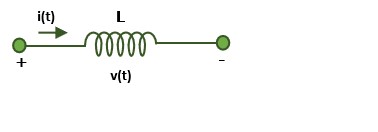
Consider a current-carrying coil. The electrical current i flowing through the coil generates a magnetic flux, denoted as NΦ, around it. This magnetic flux is directly proportional to the current −
$$\mathrm{N\phi\:\alpha\:i}$$
After removing proportional constant −
$$\mathrm{N\phi=Li}$$
$$\mathrm{L=\frac{N\phi}{i}}$$
Faraday's law of Electromagnetic Induction
Faraday's law of electromagnetic induction states that whenever a current in a conductor changes, it produces a changing magnetic flux, and this in turn induces a voltage in the conductor which opposes the current. The magnitude of this induced voltage is proportional to the rate of change of flux. Consider a coil of N turns then −
$$\mathrm{e\:=\:-\frac{d(N\phi)}{di}}$$
where e is the induced voltage, Nφ is the flux linkage in weber turns. The negative sign indicate that the induced voltage opposes the current producing the flux φ.
Types of inductance
Inductance is classified into two types −
- Self Inductance
- Mutual Inductance
Self Inductance
The voltage induced in a coil due to the change in magnetic flux created by its own current is known as self-inductance.
The flux linkage Nφ is proportional to the current in the coil and proportionality constant is termed as the self inductance, L of the coil. then −
$$\mathrm{e\:=\:\frac{d(Li)}{dt}}$$
$$\mathrm{v\:=\:L\frac{di}{dt}}$$
If the current in the conductor is constant, the voltage across the inductor will be zero, which means that the two terminals of the inductor are connected by a wire of zero resistance. This is called a short circuit between the two terminals. Hence we can say that the inductor behaves like a short circuit to DC supply.
If there is an instantaneous or sudden change in the current, the rate of change of current is infinite and the voltage across the inductor is also infinite. Hence, the inductor does not allow sudden change in current.
Mutual Inductance
The current flowing through one coil induces a voltage in an adjacent coil due to the change in magnetic flux linkage between the coils. This phenomenon is known as mutual inductance.
The voltage induced in the second coil is proportional to the rate of change of current in the first coil −
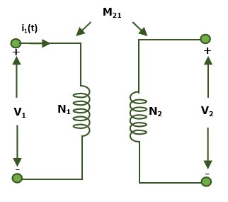
$$\mathrm{v_2\:=\:M_{21}\:\frac{di_1}{dt}}$$
The M21 indicates that the current is applied at terminals of coil 1 and the voltage is measured at coil 2. If current is applied at coil and voltage measured at coil 1, we can write −
$$\mathrm{v_1\:=\:M_{12}\:\frac{di_2}{dt}}$$
On consideration of energy in the two cases one easily prove that M21=M12. Hence we will use only one coefficient of mutual inductance M. The two coils with mutual inductance between them are said to be magnetically coupled coil. Mutual inductance is also measured in henrys. The ratio of the flux linkage to the total magnetic flux is known as the coefficient of coupling(k). And the relation between the M and k is given by −
$$\mathrm{v_1\:=\:M_{12}\:\frac{di_{2}}{dt}}$$
Factors Effecting Inductor
Practical inductors are usually made of many turns of fine wire wound in a coil to increase the magnetic effect without increasing the size of the element. The inductance of the coil given by −
$$\mathrm{L\:=\:\frac{\mu N^{2}A}{l}}$$
where A = cross sectional area of the coil is Sq. m.
N = number of turns of the coil
l = axial length of the coil in m
µ = constant of the material inside the coil called permeability and for free space or air $\mathrm{\mu\:=\:\mu_0\:=4\Pi\:x\:10^{-7}}$.
From the above discussion, Following are the factor that effect the inductor −
- Shape of the coil
- As the number of turns(N) increases inductance of the coil increase
- permeability of the coil material
- The space between the turns of the coil
- Area of cross-section of the coil
- Length of the coil
Equivalent Inductance in Parallel Combination
If two terminals of an inductor are connected to two terminal of another inductor, then the inductor are said to be in parallel. In this form, the effective inductance decreases. The voltage across the inductors remains same.
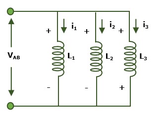
Here, the three inductor with inductance L1, L2 and L3 are connected in parallel. The voltage across the terminal is VAB, by applying kirchoff's current law, the total current is the sum of individual current inductor i.e., −
$$\mathrm{I_{Total}\:=\:I_1\:+I_2\:+I_3}$$
The voltage across an inductor is given by −
$$\mathrm{v\:=\:L\frac{d(i)}{dt}}$$
voltage across the AB terminal is given by −
$$\mathrm{V_{AB}\:=\:L_{Total}\frac{d(I_1+I_2+I_3)}{dt}}$$
$$\mathrm{\Rightarrow\: V_{AB}\:=\:L_{Total}\frac{dI_1}{dt}\:+L_{Total}\frac{dI_2}{dt}\:+L_{Total}\frac{dI_3}{dt}\:}$$
$$\mathrm{\Rightarrow\: V_{AB}\:=\:L_{Total}(\frac{dI_1}{dt}\:+ \frac{dI_2}{dt}\:+\:\frac{dI_3}{dt})}$$
$$\mathrm{\Rightarrow\: V_{AB}\:=\:L_{Total}(\frac{V}{L_1}\:+ \frac{V}{L_2}\:+\:\frac{V}{L_3})\;\:\:\:\:\:where,V_{AB}\: =\: V}$$
$$\mathrm{\Rightarrow\: \frac{1}{L_{Total}}\:=\:(\frac{1}{L_1}\:+ \frac{1}{L_2}\:+\:\frac{V}{L_3})} $$
Equivalent Inductance in Series Combination
When one inductor end is connected to another end of the inductor then the inductors are said to be connected in series. In series, the current across the inductor across the each inductor are same. The effective inductance increase in series.
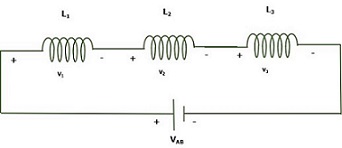
Here, the three inductors of inductance L1, L2 and L3 are connected in series. The current across the inductors are same, then by applying the kirchoff voltage law, the voltage drop is the sum of the voltage drop across each inductor −
$$\mathrm{V_{Total}\:=\:V_1\:+\:V_2\:+\:V_3}$$
voltage across the induction is given by the following equation −
$$\mathrm{V_{Total}\:=\:V_1\:+\:V_2\:+\:V_3}$$
then,
$$\mathrm{L_{Total}\frac{dI}{dt}\:=\:L_{1}\frac{dI_1}{dt}\:+L_{2}\frac{dI_2}{dt}\:+L_{3}\frac{dI_3}{dt}\:}$$
In series, I1 = I2 = I3 = I
$$\mathrm{\Rightarrow L_{Total}\frac{dI}{dt}\:= \frac{dI}{dt} (\:L_{1}\:+L_{2}\:+L_{3}\:)}$$
$$\mathrm{\Rightarrow L_{Total}\:= \:L_{1}\:+L_{2}\:+L_{3}\:}$$
Energy stored in a Inductor
The inductor stores the energy in the form of magnetic field. when current passes through an inductor, emf is induced. the work done is given by −
$$\mathrm{dW\:=\:Pdt}$$
$$\mathrm{\Rightarrow \:dW\:=\:v\:idt}$$
$$\mathrm{\Rightarrow \:dW\:=\:L \frac{di}{dt}idt}$$
applying integral on both side,
$$\mathrm{\Rightarrow \:\int dW\:=\:\int L \frac{di}{dt}idt}$$
$$\mathrm{\Rightarrow \:W\:=\:L \int i di}$$
$$\mathrm{\Rightarrow \:W\:=\:\frac{1}{2}L i^2}$$
Example: 1 A 200 turns coil has an flux of $\mathrm{(t^{3}\:-\:2t)}$ milli webers then the induced voltage across the coil is at $\mathrm{t\:=\:2sec}$.
Solution: given, N = 200 turns and $\mathrm{t\:=\:2sec}$
$\mathrm{\phi\:=\:(t^{3}\:-\:2t)\times10^{-3}}$
$\mathrm{from\:the\:equation\:,}$
$\mathrm{\phi\:\alpha\:I}$
$\mathrm{N\phi\:=\:LI}$
$\mathrm{differentiate\:with\:respective\:'t'}$
$\mathrm{N\frac{d\phi}{dt}=\:L\frac{dI}{dt}}$
$\mathrm{\Rightarrow N\frac{d(t^{3}\:-\:2t)}{dt}=\:L\frac{dI}{dt}}$
$\mathrm{\Rightarrow N(3t^{2}\:-\:t)\:=\:L\frac{dI}{dt}\:\:\:\:\:....eq1}$
we know that voltage of the inductor is given by −
$\mathrm{v\:=\:L\frac{dI}{dt}}$
from eq1
$\mathrm{v\:=\:N(3t^{2}\:-\:t)\:\:\:\:substitute\:\:t\:=2\:sec}$
$\mathrm{\Rightarrow v\:=\:200(3(2)^{2}\:-\:2)\times 10^{-3}}$
$\mathrm{\Rightarrow v\:=\:200(12\:-\:2)\times 10^{-3}}$
$\mathrm{\Rightarrow v\:=\:2000\times 10^{-3}}$
$\mathrm{\Rightarrow v\:=\:2\:v}$
Example: 2 A coil with N turns is doubled then the time constant($\mathrm{\tau\:} $) will be
a. $\mathrm{\tau\:} $
b. $\mathrm{2\tau\:} $
c. $\mathrm{4\tau\:} $
d. $\mathrm{\frac{\tau}{2}}$
Solution: let N1 = N, N2 = 2N
we know that, $\mathrm{N\:\phi\:\alpha\:i}$
$\mathrm{\Rightarrow N\:\phi\:=L\:i}$
$\mathrm{\Rightarrow N\:\alpha\:L}$
$\mathrm{\Rightarrow \frac{N_1}{N_2}\:=\:\frac{L_1}{L_2}}$
$\mathrm{\Rightarrow \frac{N}{2N}\:=\:\frac{L_1}{L_2}}$
$\mathrm{\therefore L_2\:=\:{2L_1}}$
$\mathrm{we\:know\:that, time\:constant\:\tau\:=\:\frac{L}{R}\:\:\:\:...eq1}$
$\mathrm{from\:the\:eq1,\:\frac{\tau_1}{\tau_2}=\:\frac{L_1}{L_2}}$
$\mathrm{\Rightarrow \:\frac{\tau_1}{\tau_2}=\:\frac{L_1}{2L_1}}$
$\mathrm{\Rightarrow \:2\tau_1\:=\:\tau_2}$
$\mathrm{\therefore \:\tau_2\:=\:2\tau_1}$
