- Power Electronics - Home
- Power Electronics - Introduction
- Power Electronics - Switching Devices
- Linear Circuit Elements
- Power Electronics - Resistor
- Power Electronics - Inductor
- Power Electronics - Power Diode
- Power Diode - Reverse Recovery Characteristics
- Power Electronics - BJT
- Power Electronics - IGBT
- Power Electronics - MOSFET
- Silicon Controlled Rectifier
- SCR - Switching Characteristics
- Power Electronics - TRIAC
- Power Electronics - GTO Thyristor
- Comparision of Power Semiconductor Devices
- Thyristor - Diode Model
- Thyristor - Two Transistor Model
- Thyristor - Turn ON Methods
- Thyristor - Specifications and Ratings
- Solved Example
- Phase Controlled Converters
- Power Electronics - Pulse Converters
- Effect of Source Inductance
- Performance Parameters
- Reactive Power Control of Converters
- Power Electronics - Dual Converters
- Solved Example
- DC to DC Converters
- Power Electronics - Choppers
- Power Electronics - Control Methods
- Resonant Switching
- DC Converters Solved Example
- AC to DC Converters
- Single Phase AC Voltage Controllers
- Power Electronics - Cycloconverters
- Integral Cycle Control
- Power Electronics - Matrix Converters
- Solved Example
- Power Electronics Resources
- Power Electronics - Quick Guide
- Power Electronics - Useful Resources
- Power Electronics - Discussion
Power Electronics - Choppers
A chopper uses high speed to connect and disconnect from a source load. A fixed DC voltage is applied intermittently to the source load by continuously triggering the power switch ON/OFF. The period of time for which the power switch stays ON or OFF is referred to as the choppers ON and OFF state times, respectively.
Choppers are mostly applied in electric cars, conversion of wind and solar energy, and DC motor regulators.
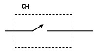
Symbol of a Chopper
Classification of Choppers
Depending on the voltage output, choppers are classified as −
- Step Up chopper (boost converter)
- Step Down Chopper(Buck converter)
- Step Up/Down Chopper (Buck-boost converter)
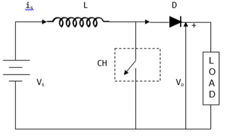
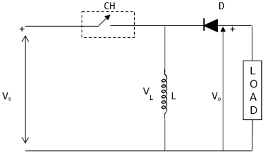
Step Up Chopper
The average voltage output (Vo) in a step up chopper is greater than the voltage input (Vs). The figure below shows a configuration of a step up chopper.
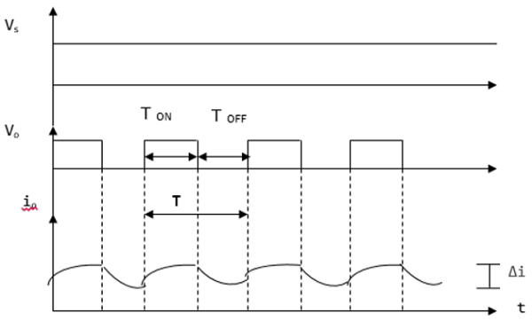
Current and Voltage Waveforms
V0 (average voltage output) is positive when chopper is switched ON and negative when the chopper is OFF as shown in the waveform below.
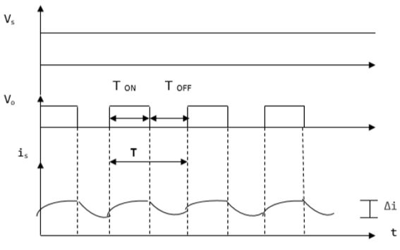
Where
TON time interval when chopper is ON
TOFF time interval when chopper is OFF
VL Load voltage
Vs Source voltage
T Chopping time period = TON + TOFF
Vo is given by −
$$V_{0}=\frac{1}{T}\int_{0}^{T_{ON}}V_{S}dt$$When the chopper (CH) is switched ON, the load is short circuited and, therefore, the voltage output for the period TON is zero. In addition, the inductor is charged during this time. This gives VS = VL
$L\frac{di}{dt}=V_{S},$ $\frac{\Delta i}{T_{ON}}=\frac{V_{S}}{L}$
Hence,$\Delta i=\frac{V_{S}}{L}T_{ON}$
Δi = is the inductor peak to peak current. When the chopper (CH) is OFF, discharge occurs through the inductor L. Therefore, the summation of the Vs and VL is given as follows −
$V_{0}=V_{S}+V_{L},\quad V_{L}=V_{0}-V_{S}$
But $L\frac{di}{dt}=V_{0}-V_{S}$
Thus,$L\frac{\Delta i}{T_{OFF}}=V_{0}-V_{S}$
This gives,$\Delta i=\frac{V_{0}-V_{S}}{L}T_{OFF}$
Equating Δi from ON state to Δi from OFF state gives −
$\frac{V_{S}}{L}T_{ON}=\frac{V_{0}-V_{S}}{L}T_{OFF}$, $V_{S}\left ( T_{ON}+T_{OFF} \right )=V_{0}T_{OFF}$
$V_{0}=\frac{TV_{S}}{T_{OFF}}=\frac{V_{S}}{\frac{\left ( T+T_{ON} \right )}{T}}$
This give the average voltage output as,
$$V_{0}=\frac{V_{S}}{1-D}$$The above equation shows that Vo can be varied from VS to infinity. It proves that the output voltage will always be more than the voltage input and hence, it boosts up or increases the voltage level.
Step Down Chopper
This is also known as a buck converter. In this chopper, the average voltage output VO is less than the input voltage VS. When the chopper is ON, VO = VS and when the chopper is off, VO = 0
When the chopper is ON −
$V_{S}=\left ( V_{L}+V_{0} \right ),\quad V_{L}=V_{S}-V_{0},\quad L\frac{di}{dt}=V_{S}-V_{0},\quad L\frac{\Delta i}{T_{ON}}=V_{s}+V_{0}$
Thus, peak-to-peak current load is given by,
$\Delta i=\frac{V_{s}-V_{0}}{L}T_{ON}$
Circuit Diagram
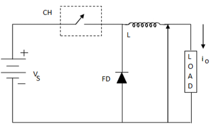
Where FD is free-wheel diode.
When the chopper is OFF, polarity reversal and discharging occurs at the inductor. The current passes through the free-wheel diode and the inductor to the load. This gives,
$$L\frac{di}{dt}=V_{0}........................................\left ( i \right )$$Rewritten as −$\quad L\frac{\Delta i}{T_{OFF}}=V_{0}$
$$\Delta i=V_{0}\frac{T_{OFF}}{L}...................................\left ( ii \right )$$Equating equations (i) and (ii) gives;
$\frac{V_{S}-V_{0}}{L}T_{ON}=\frac{V_{0}}{L}T_{OFF}$
$\frac{V_{S}-V_{0}}{V_{0}}=\frac{T_{OFF}}{T_{ON}}$
$\frac{V_{S}}{V_{0}}=\frac{T_{ON}-T_{OFF}}{T_{ON}}$
The above equation gives;
$$V_{0}=\frac{T_{ON}}{T}V_{S}=DV_{S}$$Equation (i) gives −
$\Delta i=\frac{V_{S}-DV_{S}}{L}DT$, from $D=\frac{T_{ON}}{T}$
$=\frac{V_{S}-\left ( 1-D \right )D}{Lf}$
$f=\frac{1}{T}=$chopping frequency
Current and Voltage Waveforms
The current and voltage waveforms are given below −
For a step down chopper the voltage output is always less than the voltage input. This is shown by the waveform below.
Step Up/ Step Down Chopper
This is also known as a buck-boost converter. It makes it possible to increase or reduce the voltage input level. The diagram below shows a buck-boost chopper.
When the chopper is switched ON, the inductor L becomes charged by the source voltage Vs. Therefore, Vs = VL.
$$L\frac{di}{dt}=V_{S}$$ $$\Delta i=\frac{V_{S}}{L}T_{ON}=\frac{V_{S}}{L}T\frac{T_{ON}}{T}=\frac{DV_{S}}{Lf}$$Because −
$D=\frac{T_{ON}}{T}$ and $f=\frac{1}{T} .............................................. \left ( iii \right )$
When the chopper is switched OFF, the inductors polarity reverses and this causes it to discharge through the diode and the load.
Hence,
$$V_{0}=-V_{L}$$ $$L\frac{di}{dt}=-V_{0}$$$L\frac{\Delta i}{T_{OFF}}=-V_{0}$, thus $\Delta i=-\frac{V_{0}}{L}T_{OFF}................................\left ( iv \right )$
Evaluating equation (iii) and (iv) gives −
$\frac{DV_{S}}{Lf}=-\frac{V_{0}}{L}T_{OFF}$, $DV_{S}=-DV_{S}=-V_{0}T_{OFF}f$
$DV_{S}=-V_{0}\frac{T-T_{ON}}{T}=-V_{0}\left ( 1-\frac{T_{ON}}{T} \right )$, $V_{0}=-\frac{DV_{S}}{1-D}$
Because $D=\frac{T_{ON}}{T}=\frac{T-T_{OFF}}{1-D}$
This gives,
$V_{0}=\frac{DV_{S}}{1-D}$
D can be varied from 0 to 1. When, D = 0; VO = 0
When D = 0.5, VO = VS
When, D = 1, VO = ∞.
Hence, in the interval 0 ≤ D ≤ 0.5, output voltage varies in the range 0 ≤ VO < VS and we get step down or Buck operation. Whereas, in the interval 0.5 D 1, output voltage varies in the range VS ≤ VO ≤ ∞ and we get step up or Boost operation.
