- Power Electronics - Home
- Power Electronics - Introduction
- Power Electronics - Switching Devices
- Linear Circuit Elements
- Power Electronics - Resistor
- Power Electronics - Inductor
- Power Electronics - Power Diode
- Power Diode - Reverse Recovery Characteristics
- Power Electronics - BJT
- Power Electronics - IGBT
- Power Electronics - MOSFET
- Silicon Controlled Rectifier
- SCR - Switching Characteristics
- Power Electronics - TRIAC
- Power Electronics - GTO Thyristor
- Comparision of Power Semiconductor Devices
- Thyristor - Diode Model
- Thyristor - Two Transistor Model
- Thyristor - Turn ON Methods
- Thyristor - Specifications and Ratings
- Solved Example
- Phase Controlled Converters
- Power Electronics - Pulse Converters
- Effect of Source Inductance
- Performance Parameters
- Reactive Power Control of Converters
- Power Electronics - Dual Converters
- Solved Example
- DC to DC Converters
- Power Electronics - Choppers
- Power Electronics - Control Methods
- Resonant Switching
- DC Converters Solved Example
- AC to DC Converters
- Single Phase AC Voltage Controllers
- Power Electronics - Cycloconverters
- Integral Cycle Control
- Power Electronics - Matrix Converters
- Solved Example
- Power Electronics Resources
- Power Electronics - Quick Guide
- Power Electronics - Useful Resources
- Power Electronics - Discussion
Power Electronics - Power Diodes
A Power Diode is a type of diode commonly used in power electronic circuits. Similar to a regular diode, a power diode has two terminals and allows current to flow in one direction. However, its construction differs from that of a standard diode, enabling it to handle higher current and voltage levels. A power diode operates as a uni-polar and unidirectional switch. It is an uncontrolled device because its turn-on and turn-off are determined by the applied supply voltage and current.
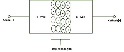
Structure of Signal Diode
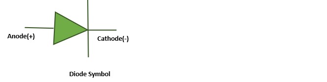
Signal Diodes are the simplest semiconductor device having only two layers, two terminals and one junction. The signal diode have a junction formed by p-type semi-conductor and n-type semi conductor, the lead joining p-type is known as anode and the other side lead joining the n-type is known as cathode. Following is the structure of an signal diode −
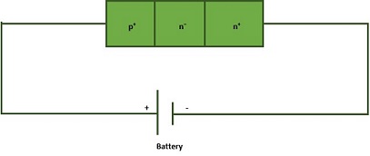
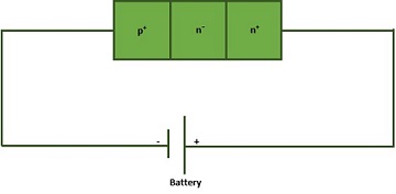
Structure of Power Diode
Power diodes are also similar to regular diodes, although they vary slightly in their construction. In regular diodes, the doping level of both p-type and n-type is same and hence we get a PN junction, but in power diodes we have a junction formed between a heavily dopped p+ and a lightly doped n- and the layer which is epitaxially grown on a heavily doped n+ layer. Following is the structure −
The n- layer is the key feature of the power diode which makes it suitable for high power applications. This layer is very lightly doped, almost intrinsic and hence the device is also is also known as a PIN diode, where I stands for intrinsic(pure/free from impurities).
Operation of Power diode
Following are two different modes of operation of Power diode −
- Forward biased
- Reverse biased
Forward biased
When the anode terminal of the diode is connected to the positive terminal of the supply and the cathode terminal is connected to the negative terminal, the diode is said to be in forward biased. Under this condition, the diode conducts current and it acts as a ON switch.
In forward bias, the holes from the p+ layers enters into n- layer there by the resistivity of n- layer decreases.
The process of decreasing the resistivity of n- layer by injecting holes is called conductivity modulation.
Reverse biased
When the anode terminal of the diode is connected to the negative terminal of the supply and the cathode terminal is connected to the positive terminal, the diode is said to be in reverse biased. Under this condition, the diode does not conduct current and it acts as a OFF switch.
Practically in reverse biased condition the diode blocks the voltage but very small leakage current flow through diode. However, if we exceed the reverse break-over voltage then breakdown occurs and device will permanently gets damaged. In this reverse blocking state we can model the diode as parallel place capacitor.
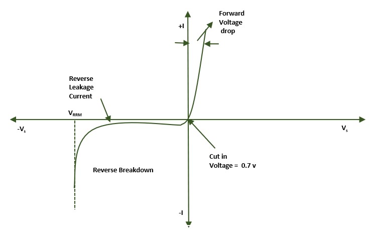
Power Diode V-I Characteristics
The V I characteristics of the power diode is similar to that of a signal diode. When the diode is forward bias, with increase of the source voltage Vs from zero value, initially diode current is zero.
From Vs = 0 to cut-in voltage, the forward-diode current is very small. The cut-in voltage is also known as threshold voltage or turn-on voltage. Beyond cut-in voltage, the diode current raises rapidly and the diode is in conduction mode. The cut-in voltage is around 0.7 v for silicon diode.
In the reverse biased condition of the diode, a small reverse current, called leakage current, of the order of micro-amperes or milli-amperes flows. The leakage current increases slowly with the reverse voltage until breakdown or avalanche voltage is reached.
At this breakdown voltage, diode is turned ON in reverse direction. If current in the reversed direction is not limited by a series resistance, the current will become quit high, which damages the diode.
The power diodes are now available with forward current rating of 1 A to several thousand amperes and with reverse voltage ratings of 50 V to 3000V or more.