- Power Electronics - Home
- Power Electronics - Introduction
- Power Electronics - Switching Devices
- Linear Circuit Elements
- Power Electronics - Resistor
- Power Electronics - Inductor
- Power Electronics - Power Diode
- Power Diode - Reverse Recovery Characteristics
- Power Electronics - BJT
- Power Electronics - IGBT
- Power Electronics - MOSFET
- Silicon Controlled Rectifier
- SCR - Switching Characteristics
- Power Electronics - TRIAC
- Power Electronics - GTO Thyristor
- Comparision of Power Semiconductor Devices
- Thyristor - Diode Model
- Thyristor - Two Transistor Model
- Thyristor - Turn ON Methods
- Thyristor - Specifications and Ratings
- Solved Example
- Phase Controlled Converters
- Power Electronics - Pulse Converters
- Effect of Source Inductance
- Performance Parameters
- Reactive Power Control of Converters
- Power Electronics - Dual Converters
- Solved Example
- DC to DC Converters
- Power Electronics - Choppers
- Power Electronics - Control Methods
- Resonant Switching
- DC Converters Solved Example
- AC to DC Converters
- Single Phase AC Voltage Controllers
- Power Electronics - Cycloconverters
- Integral Cycle Control
- Power Electronics - Matrix Converters
- Solved Example
- Power Electronics Resources
- Power Electronics - Quick Guide
- Power Electronics - Useful Resources
- Power Electronics - Discussion
Power Electronics - Pulse Converters
Phase Controlled Converter
A phase controlled converter converts AC to DC energy (line commutated). In other words, it is used in the conversion of fixed-frequency and fixed-voltage AC power into variable DC voltage output. It is expressed as
Fixed Input − Voltage, frequency and AC power
Variable output − DC voltage output
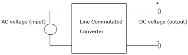
The AC input voltage that goes into a converter is normally at fixed RMS (root mean square) and fixed frequency. The inclusion of phase-controlled thyristors in the converter ensures that a variable DC output voltage is obtained. This is made possible by altering the phase angle at which the thyristors are triggered. As a result, a pulsating waveform of the load current is obtained.
During the input supply half cycle, the thyristor is in forward bias and is switched ON via the application of sufficient gate pulse (trigger). Current starts to flow once the thyristor has been switched ON, that is, at a point ωt=α to point ωt=β. The moment the load current drops to zero, the thyristor switches OFF as a result of line (natural) commutation.
There are a number of power converters that utilize natural commutation. These include −
- AC to DC converters
- AC to AC converters
- AC voltage controllers
- Cycloconverters
The above power converters will be explained in the next chapters in this tutorial.
2- Pulse Converter
A 2-phase pulse converter, also known as a level 2 pulse width modulator (PWM) generator, is used to generate pulses for pulse width modulation converters that are carrier based. It does this by utilizing level-two topology. This block controls switching devices for control purposes like IGBTs and FETs that exist in three types of converters namely −
- 1 arm (single phase half bridge)
- 2 arms (single phase full bridge)
- 3 arms ( three phase bridge)
The reference input signal in a 2-pulse converter is compared to a carrier. If the reference input signal is more than the carrier, the pulse equals to 1 for the upper device and 0 for the lower device.
In order to control a device with a single-phase full bridge (2 arms), it is necessary to apply unipolar or bipolar pulse width modulation. In unipolar modulation each of the two arms is independently controlled. A second reference input signal is generated internally through a shift in initial reference point by 180°
When the bipolar PWM is applied, the state of the lower switching device in the second single phase full bridge is similar to the upper switch in the first single phase full bridge device. Using a unipolar modulation leads to smooth AC waveforms while the bipolar modulation results in less varying voltage.
3-Pulse Converter
Consider a three-phase 3-pulse converter, where each of the thyristor is in conduction mode during the third of the supply cycle. The earliest time a thyristor is triggered into conduction is at 30° in reference to the phase voltage.
Its operation is explained using three thyristors and three diodes. When the thyristors T1, T2 and T3 are replaced by diodes D1, D2 and D3, conduction will begin at angle 30° in respect to the phase voltages uan, ubn and ucn respectively. Therefore, the firing angle α is measured initially at 30° in reference to the phase voltage corresponding to it.
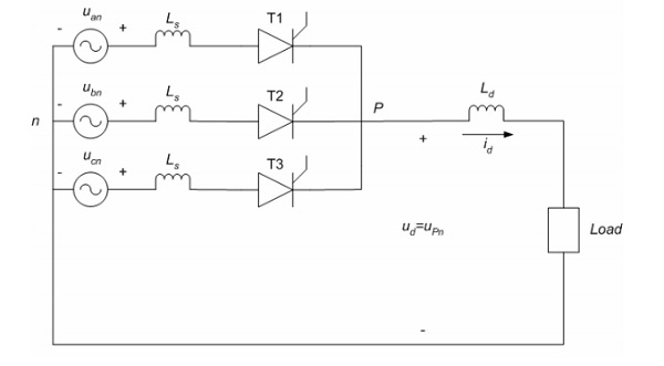
The current can only flow in one direction through the thyristor, which is similar to inverter mode of functioning where power flows from the DC side to the AC side. In addition, the voltage in the thyristors is controlled by controlling the firing angle. This is achieved when α = 0(possible in a rectifier). Thus, the 3-pulse converter acts as an inverter and a rectifier.
6-Pulse Converter
The figure below shows a six-pulse bridge controlled converter connected to a three-phase source. In this converter, the number of pulses is twice that of phases, that is p = 2m. Using the same converter configuration, it is possible to combine two bridges of the six-pulse to obtain a twelve or more pulses converter.
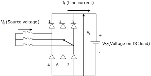
When commutation is not available, two diodes will conduct at any particular time. Furthermore, to obtain a voltage drop across the load, two diodes must be at positioned at opposite legs of the bridge. For example, diodes 3 and 6 cannot be ON at the same time. Therefore, the voltage drop across the DC load is a combination of line voltage VL from the three-phase source.
It is important to note that more the number of pulses, the greater the utilization of the converter. In addition, the fewer the number of pulses the lesser the utilization of the converter.
