- Power Electronics - Home
- Power Electronics - Introduction
- Power Electronics - Switching Devices
- Linear Circuit Elements
- Power Electronics - Resistor
- Power Electronics - Inductor
- Power Electronics - Power Diode
- Power Diode - Reverse Recovery Characteristics
- Power Electronics - BJT
- Power Electronics - IGBT
- Power Electronics - MOSFET
- Silicon Controlled Rectifier
- SCR - Switching Characteristics
- Power Electronics - TRIAC
- Power Electronics - GTO Thyristor
- Comparision of Power Semiconductor Devices
- Thyristor - Diode Model
- Thyristor - Two Transistor Model
- Thyristor - Turn ON Methods
- Thyristor - Specifications and Ratings
- Solved Example
- Phase Controlled Converters
- Power Electronics - Pulse Converters
- Effect of Source Inductance
- Performance Parameters
- Reactive Power Control of Converters
- Power Electronics - Dual Converters
- Solved Example
- DC to DC Converters
- Power Electronics - Choppers
- Power Electronics - Control Methods
- Resonant Switching
- DC Converters Solved Example
- AC to DC Converters
- Single Phase AC Voltage Controllers
- Power Electronics - Cycloconverters
- Integral Cycle Control
- Power Electronics - Matrix Converters
- Solved Example
- Power Electronics Resources
- Power Electronics - Quick Guide
- Power Electronics - Useful Resources
- Power Electronics - Discussion
Diode Reverse Recovery Characteristics
The reverse recovery characteristics of a diode describe its behavior during the transition from the conducting (ON) state to the non-conducting (OFF) state. The reverse recovery time trr is defined as the time between the instant forward diode current becomes zero and the instant recovery current decays to 25% of its reverse peak value IRM.
The reverse recovery time is composed of two segments of time ta and tb, i.e.,trr = ta + tb. The ta is the time between zero crossing of forward current and peak reverse current IRM. During the time ta, charge stored in the depletion region is removed. Time tb is measured from the instant IRM to the instant where 0.25IRM is reached. During tb, charge from the two semiconductor layers is removed.
Softness Factor(s)
The ratio of tb/ta is called the softness factor or S-factor. This factor is a measure of the voltage transients that occur during the diode recovers. A diode with S-factor equal to one is called soft-recovery diode and a diode with S-factor less than one is called snappy-recovery diode or fast-recovery diode.
case 1: If s=1, ta=tb
$$\mathrm{t_{rr}=t_a +t_b}$$
$\mathrm{\Rightarrow t_{rr}=t_a + st_a\:\:\:\:where,\:\:t_b=st_a }$$
$$\mathrm{\Rightarrow t_{rr}=\:t_a[1+s]}$$
case 2: If s<<1, then ,tb<<tb then,
$$\mathrm{\Rightarrow t_{rr}\approx\:t_a}$$
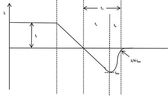
From the characteristics peak inverse current IRM can be expressed as −
$$\mathrm{I_{RM} = t_a \frac{di}{dt} \:\:\:\:\: ....\:\: eq\:1\:\:\:\:(from \:curve)}$$
Where $\mathrm{\frac{di}{dt}} $ is the rate of change of reverse current. From the characteristics, the storage charge QR can be expressed as −
$$\mathrm{Q_R = \frac{1}{2} t_{rr} I_{RM}\:\:\:\:\: ....\:\:eq\:2}$$
$$\mathrm{\Rightarrow I_{RM}= \frac{2Q_R }{t_{rr}}\:\:\:\:\: ....eq\:3}$$
Equating, eq 1 and eq 2 −
$$\mathrm{t_{rr} \frac{di}{dt}= \frac{2Q_R}{t_{rr}}\:\:\:\:\: where, t_a=t_{rr}}$$
$$\mathrm{\Rightarrow t_{rr}^{2} = \frac{2Q_R}{\frac{di}{dt}}}$$
$$\mathrm{\Rightarrow t_{rr} = \sqrt{\frac{2Q_R}{\frac{di}{dt}}}}$$
Replacing trr in equation 1, then −
$$\mathrm{I_{RM} = \sqrt{\frac{2Q_R}{(\frac{di}{dt})}}(\frac{di}{dt})} $$
$$\mathrm{\Rightarrow I_{RM} = \sqrt{\frac{2Q_R}{(\frac{di}{dt})}(\frac{di}{dt}^2)}}$$
$$\mathrm{\Rightarrow I_{RM} = \sqrt{2Q_R(\frac{di}{dt})}}$$
then, storage charge QR can be expressed in terms of trr−
$$\mathrm{Q_R = \frac{1}{2} t_{rr} I_{RM}}$$
$$\mathrm{\Rightarrow Q_R = \frac{1}{2}(\frac{di}{dt})t_{rr}^2} $$
Example: A power diode has $\mathrm{\frac{di_a}{dt}\:=\: 50A/\mu sec}$ and softness factor[s] = 0.3, trr= 3.9$\mathrm{\mu sec}$. Find −
(a). IRM
(b). QRR
Solution: $$\mathrm{given,\:Soft-factor(s)\:of\:Power\:diode\:=\:0.3\\reverse\:recovery\:time(t_{rr})\:=\:3.9\mu sec \\rate\:of\:change\:anode\:current\frac{di_a}{dt}\:=\:50{A}/{sec} \\ I_{RM}\:=\:\frac{t_{rr}}{1+s}\frac{di_a}{dt}\:\:\:\:\:Q_R = \frac{1}{2}(\frac{di}{dt})\frac{t_{rr}^2}{1+s} \\ \Rightarrow \:\frac{3.9\:\times\:10^{-6}\:\times\:50}{1.3\:\times\:10^{-6}}\:\:\:\:\:\:\: \Rightarrow\: \frac{1\:\times\:3.9^2\:\times\:50}{2\:\times\:1.3} \\ \Rightarrow \: I_{RM}\:=\:150\:A\:\:\:\:\: \Rightarrow\: Q_{R}\:=\:292.5\mu c \\ }$$
Types of Power Diode
Diodes are classified according to their reverse recovery characteristics. The three types of power diodes are −
- General purpose diodes
- Fast recovery diodes
- Schottky diodes
General -purpose Diodes
These diodes have relatively high reverse recovery time, of the order of about 25 µs. The current rating vary from 1 A to several thousand amperes and the range of voltage rating is from 50 V to about 5kV. Battery charging, electric traction, electroplating, welding and uninterruptible power supplies(UPS) are some applications of this diode.
Fast-recovery Diodes
These diodes has low recovery time about 5µs or less. These are used in choppers, commutation circuits, switched mode power supplies, induction heating etc. Their current ratings vary from about 1 A to several thousand amperes and voltage ratings from 50 V to above 3 kV.
Schottky Diodes
These diodes use metal to semiconductor junction for rectification purposes instead of p n-junction. Schottky diodes are characterized by very fast recovery time and low forward voltage drop. The reverse voltage ratings are limited to about 100 V and forward current ratings vary from 1 A to 300 A. Applications of Schottky diodes include high-frequency instrumentation and switching power supplies.
