- Power Electronics - Home
- Power Electronics - Introduction
- Power Electronics - Switching Devices
- Linear Circuit Elements
- Power Electronics - Resistor
- Power Electronics - Inductor
- Power Electronics - Power Diode
- Power Diode - Reverse Recovery Characteristics
- Power Electronics - BJT
- Power Electronics - IGBT
- Power Electronics - MOSFET
- Silicon Controlled Rectifier
- SCR - Switching Characteristics
- Power Electronics - TRIAC
- Power Electronics - GTO Thyristor
- Comparision of Power Semiconductor Devices
- Thyristor - Diode Model
- Thyristor - Two Transistor Model
- Thyristor - Turn ON Methods
- Thyristor - Specifications and Ratings
- Solved Example
- Phase Controlled Converters
- Power Electronics - Pulse Converters
- Effect of Source Inductance
- Performance Parameters
- Reactive Power Control of Converters
- Power Electronics - Dual Converters
- Solved Example
- DC to DC Converters
- Power Electronics - Choppers
- Power Electronics - Control Methods
- Resonant Switching
- DC Converters Solved Example
- AC to DC Converters
- Single Phase AC Voltage Controllers
- Power Electronics - Cycloconverters
- Integral Cycle Control
- Power Electronics - Matrix Converters
- Solved Example
- Power Electronics Resources
- Power Electronics - Quick Guide
- Power Electronics - Useful Resources
- Power Electronics - Discussion
Power Electronics - Resistor
Resist is the word which means to oppose. Resistance is the property of opposing the flow of electrons, in a conductor or a semiconductor. A Resistor is an passive element, which has the property of resistance.
The mathematical model for a resistor is described by the famous Ohm's law for most of the conducting materials. Ohm's law states that, The voltage across any conducting material is directly proportional to the current flowing through the conductor −
v ∝ i
when proportional symbol is removed we get −
v = Ri
Where R is the proportionality constant is called resistance of the material.
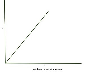
V-I characteristics of a resistor
The characteristics of a resistor are linear as the voltage is directly proportional to the current element −
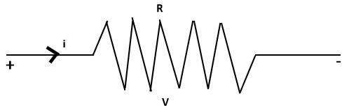
The network symbol and the polarities of voltage and current for absorbing power in a resistor as shown below −
The resistance of a wire of length 'l' meters, and a cross sectional area of A Sq.m. is given by −
$$\mathrm{R\:=\:\rho\:\frac{l}{A}\:\Omega}$$
where, is the resistivity of the wire in ohm-meters. The reciprocal of the resistance is defined as conductance and the unit of conductance is Siemens(S). Thus , conductance is the ratio of current to voltage −
$$\mathrm{G\:=\:\frac{1}{R}\:\mho}$$
Effect of heating on Resistance
Consider a conductor, if the length of the conductor is increased by n times by heating effect than the new resistance is given by −
$$\mathrm{R_{(new)}\:=\:n^2 R_{(old)}}$$
Following is the proof of above, consider R = resistance, l = length of the conductor and a = area of cross section −
$$\mathrm{R_1\:=\:\rho\:\frac{l_1}{A_1}\:\Omega\:\:\:\:\:..eq1}$$
$$\mathrm{R_2\:=\:\rho\:\frac{nl_1}{A_2}\:\Omega\:\:\:\:\:..eq2}$$
Here, volume is constant so area*length = constant :
$$\mathrm{A_1\:\times\:l_1\:=\:A_2\:\times\:l_2}\:\:\:\:\: substitute\:l_2\:=\:n\:l_1$$
$$\mathrm{\Rightarrow A_1\:\times\:l_1\:=\:A_2\:\times\:n\:l_1}$$
$$\mathrm{\Rightarrow A_2\:=\:\frac{A_1}{n}\:\:\:\:\:..eq3} $$
Now substitute eq3 in eq2
$$\mathrm{R_2\:=\:\rho\:\frac{n\:l_1\:n}{A_1}\:\Omega}$$
$$\mathrm{R_2\:=\:n^2\:R_1\:\:\:\:\:where\:R_1\:=\:\:\rho\:\frac{l_1}{A_1}}$$
$$\mathrm{\therefore\:R_{new}\:=\:n^2\:R_{old}}$$
Effect of Temperature on Resistance
The resistance of the conductor is inversely proportional to the temperature i.e. as the temperature increases the resistance decreases. Consider R is the resistance and the t is the temperature in Celsius −
$$\mathrm{R\:\alpha\:\frac{1}{t^oC}}$$
The mathematical representation of the resistance and temperature is shown below −
$$\mathrm{At\:\:t\:=\:t_1,\:R_i\:=R_0}$$
$$\mathrm{At\:\:t\:=\:t_2,\:R_t\:=R_0(1\:+\:\alpha\Delta\:t)}$$
$$\mathrm{where,\:\Delta\:t\:=\:(t_2\:-\:t_1)^0C}$$
α = Temperature coefficient/oC
Example − An incandescent lamp is marked 40W, 240v. If resistance at room temperature(26oC) is 120 Ω and temperature cofficient of resistance is 4.5x10⁻³/oC, then its ON state filament temperature in oC is approximately?
Solution − Given, Power of the incandescent lamp = 40W
Rated voltage of the incandescent lamp = 240v
Temperature coefficient of resistance = 4.5x10⁻³/oC
$\mathrm{P_b\:=\: \frac{V^2}{R_b}\:\:Watt} \\ \mathrm{\Rightarrow R_b\:=\: \frac{V^2}{P_b}\:\:\Omega} \\ \mathrm{\Rightarrow R_b\:=\: \frac{420^2}{10}\:\:\Omega} \\ \mathrm{\Rightarrow R_b\:=\:1440\:\:\Omega} \\ \mathrm{R_t\:=R_0(1\:+\:\alpha\Delta\:t)\:\:\Omega} \\ \mathrm{1440\:=\:120(1\:+\:\alpha\Delta\:t)\:\:\Omega} \\ \mathrm{12\:=\:1\:+\:\alpha\Delta\:t\:\:} \\ \mathrm{\frac{11}{\alpha}\:=\:\Delta\:t} \\ \mathrm{\frac{11}{\alpha}\:=\:t_2\:-\:t_2} \\ \mathrm{\frac{11000}{4.5}\:=\:t_2\:-\:26} \\ \mathrm{\frac{11000}{4.5}\:=\:t_2\:-\:26} \\ \mathrm{t_2\:=\:2444.44\:+\:26} \\ \mathrm{t_2\:=\:2470.44\:^0C} \\ \mathrm{\therefore\:incandescent\:lamp\:ON\:state\: filament\:temperature\:is\:2470.4^0C}$
Calculating Equivalent Resistance for Series Circuits
Equivalent resistance refers to the overall resistance resulting from the combination of all resistances within a circuit. If n resistances are added to the circuit, either in series or parallel, and if we substitute all these resistances with a single resistance in a manner that the current and voltage difference in the circuit remain unchanged, it is termed as equivalent resistance.
In series circuits, the current flowing through all components is the same, as there is only one path for the current to travel. For example, if we connect a multiple bulbs in series. If one bulb fuse, all the bulbs do not light up.
In a series circuits, when n(n>1) resistors are interconnected connected consecutively, allowing the entire set to be substituted by a single equivalent resistor with an identical resistance value. In this configuration, the equivalent resistance is the sum of the individual resistances. While the current remains constant across each resistor, the voltage is distributed into n segments among the resistors.

The formula for equivalent resistance(Req) in a series combination is given by −
$$\mathrm{R_{eq}\:=\:R_1\:+\:R_2\:+\:R_3\:+\:R_4\:+\:....\:+\: R_n}$$
where, Req is equivalent resistance and R1, R2, R3 are connected consecutively. Rn represents the resistance of the nth resistor.
Example: What is the equivalent resistance if the four resistances of 3Ω, 5?Ω, 9Ω and 2Ω are connected in series?
Solution: Given resistances connected in series: R1 = 3Ω, R2 = 5Ω, R3 = 9Ω and R4 = 2Ω
$\mathrm{R_{eq}\:=\:R_1\:+\:R_2\:+\:R_3\:+\:R_4\:+\:....\:+\: R_n} \\ \mathrm{R_{eq}\:=\:R_1\:+\:R_2\:+\:R_3\:+\:R_4\:} \\ \mathrm{R_{eq}\:=\:3\Omega\:+\:5\Omega\:+\:9\Omega\:+\:2\Omega\:} \\ \mathrm{R_{eq}\:=\:19\Omega\:} $
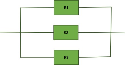
Calculating Equivalent Resistance for Parallel Circuits
In Parallel circuits, the current flow's through multiple paths and the voltage across the components remains the same. For example, if we connect a multiple bulbs in parallel. If one bulb fuse, the remaining bulbs will continue to light up as each has an independent path for current flow.
When n(n>1) resistors are connected in parallel, then the entire set can be substituted by a single equivalent resistor with an identical resistance value. In this configuration, the reciprocal of equivalent resistance is the sum of the reciprocals of individual resistances. While the voltage remains constant across each resistor, the current is distributed into n segments among the resistors.
The formula for equivalent resistance(Req) in a parallel combination is given by −
$$\mathrm{\frac{1}{R_{eq}}\:=\:\frac{1}{R_1}\:+\:\frac{1}{R_2}\:+\:\frac{1}{R_3}\:+\:\frac{1}{R_4}\:+\:....\:+\: \frac{1}{R_n}}$$
where, Req is equivalent resistance and R1, R2, R3 are connected in parallel. Rn represents the resistance of the nth resistor.
Example: What is the equivalent resistance if three resistances of 6Ω, 3Ω, and 8 Ω are connected in parallel?
Solution: Given resistances connected in parallel: R1 = 6Ω, R2 = 3Ω, R3 = 8Ω
$\mathrm{\frac{1}{R_{eq}}\:=\:\frac{1}{R_1}\:+\:\frac{1}{R_2}\:+\:\frac{1}{R_3}\:+\:\frac{1}{R_4}\:+\:....\:+\: \frac{1}{R_n}} \\ \mathrm{\frac{1}{R_{eq}}\:=\:\frac{1}{R_1}\:+\:\frac{1}{R_2}\:+\:\frac{1}{R_3}\:+\:\frac{1}{R_4}\:+\:....\:+\: \frac{1}{R_n}} \\ \mathrm{\frac{1}{R_{eq}}\:=\:\frac{1}{6}\Omega\:+\:\frac{1}{3}\Omega\:+\:\frac{1}{8}\Omega\:} \\ \mathrm{\frac{1}{R_{eq}}\:=\:\frac{4\:+\:8\:+3}{24}\Omega\:} \\ \mathrm{\frac{1}{R_{eq}}\:=\:\frac{15}{24}\Omega\:} \\ \mathrm{R_{eq}\:=\:\frac{24}{15}\Omega\:} \\ \mathrm{R_{eq}\:=\:1.6\Omega\:} \\ $
Resistor Color Coding
A process called color coding is used to determine the value of resistance for a resistor, just as shown in the above figure. A resistor is coated with four color bands where each color determines a particular value. The below table shows a list of values which each color indicates.
| COLOUR | DIGIT | MULTIPLIER | TOLERANCE |
|---|---|---|---|
| Black | 0 | 100 = 1 | |
| Brown | 1 | 101 = 10 | 1 |
| Red | 2 | 102 = 100 | 2 |
| Orange | 3 | 103 = 1000 | |
| Yellow | 4 | 104 = 10000 | |
| Green | 5 | 105 = 100000 | 0.5 |
| Blue | 6 | 106 = 1000000 | 0.25 |
| Violet | 7 | 107 = 10000000 | 0.1 |
| Gray | 8 | 108 = 100000000 | |
| White | 9 | 109 = 1000000000 | |
| Gold | 10-1 = 0.1 | 5 | |
| Silver | 10-2 = 0.01 | 10 | |
| none | 20 |
The first two colored bands indicate the first and second digit of the value and the third color band represents the multiplier number of zeroes added . The fourth color band indicates the tolerance value.
Tolerance is the range of value up to which a resistor can withstand without getting destroyed. This is an important factor. The following figure shows how the value of a resistor is determined by color code.
The five color band resistors are manufactured with tolerance of 2% and 1% and also for other high accuracy resistors. In these five band resistors, the first three bands represent digits, fourth one indicates multiplier and the fifth represents tolerance.
Let us look at an example to understand the color coding process.
Example: Determine the value of a resistor with a color code yellow, blue, orange and silver.
Solution: The value of yellow is 4, blue is 6, orange is 3 which represents multiplier. Silver is 10 which is the tolerance value.
Hence the value of the resistor is 46x103 = 46kΩ
The maximum resistance value for this resistor is
46kΩ or 46000Ω + 10% = 46000 + 4600 = 50600Ω = 50.6kΩ
The minimum resistance value for this resistor is
46kΩ or 46000Ω - 10% = 46000 - 4600 = 41400Ω = 41.4kΩ
