- BEEE - Home
- BEEE - Introduction
- Basic Electrical Quantities
- Ohm's Law
- Kirchhoff's Current Law
- Kirchhoff's Voltage Law
- Types of Circuit Elements
- Series Circuit
- Parallel Circuit
- Voltage Division and Voltage Divider
- Current Division and Current Divider
- Star and Delta Connection
- Electric Power and Electrical Energy
- Effects of Electric Current
- Electrical Safety Measures
- DC Circuits and Network Theorems
- Basics of DC Circuits
- Nodal Analysis
- Mesh Analysis
- Thevenin's Theorem
- Norton's Theorem
- Superposition Theorem
- Maximum Power Transfer Theorem
- Source Transformation
- BEEE Useful Resources
- BEEE - Useful Resources
- BEEE - Discussion
Thevenin's Theorem
Thevenin's Theorem is an important network theorem, widely used in analyzing electric circuits, finding currents, voltages, and power. We generally use basic circuit laws such as Ohm's law, KCL, KVL, etc. to solve electric circuits, but when a circuit becomes complex, then using these simple methods is not practical. In such cases, we use advanced methods like Thevenin's Theorem. Read this chapter to get a good understanding of Thevenin's Theorem and how it is applied.
Thevenin's Theorem Statement
Thevenin's Theorem states that any two terminal linear network or circuit can be represented with an equivalent network or circuit, which consists of a voltage source in series with a resistor. This equivalent circuit is termed as Thevenin's Equivalent Circuit.
A linear circuit may contain independent sources, dependent sources, and resistors. If a circuit contains multiple independent sources, dependent sources, and resistors, then the response in an element can be easily found by replacing the entire network with the Thevenin's equivalent network across the element's terminals. The response in the element can be the voltage across that element, current flowing through that element, or power dissipated across that element.
Thevenin's Equivalent Circuit
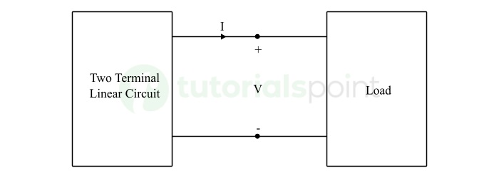
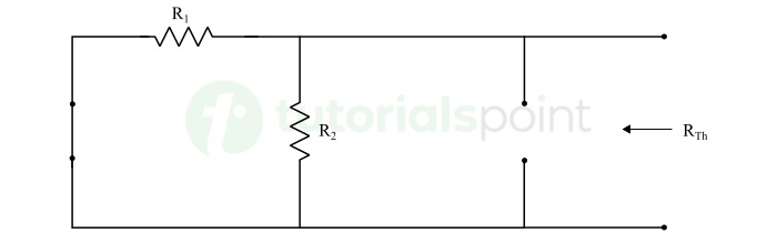
Consider a complex two terminal linear network with a load element, as shown in the following figure −
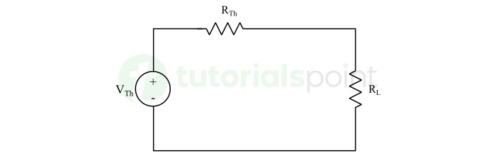
Here, the two-terminal network can be replaced by an equivalent practical voltage source, as shown in the figure below.
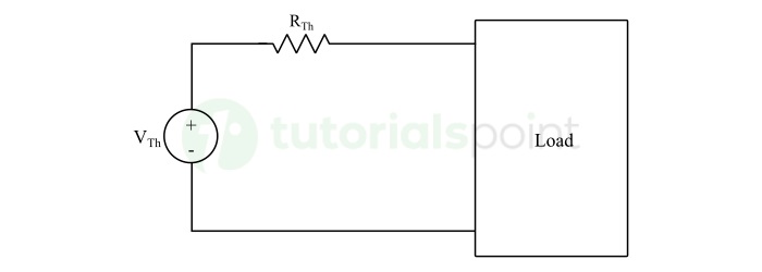
Thevenin's Equivalent Circuit resembles a practical voltage source, i.e., it has a voltage source in series with a resistor. Where,
- The voltage source present in the Thevenin's equivalent circuit is called as Thevenin's equivalent voltage or simply Thevenin's voltage, denoted by VTh.
- The resistor present in the Thevenin's equivalent circuit is called as Thevenin's equivalent resistor or simply Thevenin's resistor, denoted by RTh.
Procedure of Thevenin's Theorem
The step-by-step procedure for solving electric circuits using Thevenin's Theorem is explained here −
Step 1 − First of all, remove the circuit element/load element across which we need to find the response. In other words, open the load terminals by removing the element.
Step 2 − Find Thevenin's voltage VTh which is nothing but voltage across the open circuited load terminals in the above circuit.
Step 3 − Find Thevenin's resistance RTh looking from the open circuited load terminals by eliminating all the independent sources present in the circuit. Replace ideal voltage sources by short-circuit and ideal current sources by open circuits.
Step 4 − Finally, draw the Thevenin's equivalent circuit by connecting the Thevenin's voltage VTh in series with the Thevenin's resistance RTh. Reconnect the load element across the terminals and determine the required response in the load.
After getting a theoretical explanation, let us now understand the application of Thevenin's theorem through an example.
Circuit Analysis Using Thevenin's Theorem
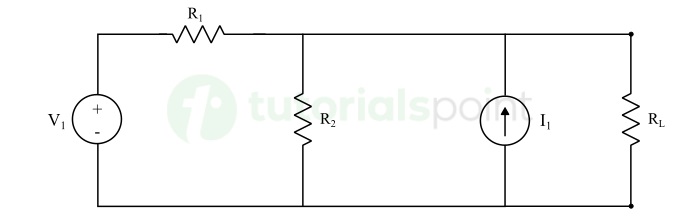
In the circuit shown below, find the current flowing through and the voltage across the 20 Ω resistor using Thevenin's Theorem.
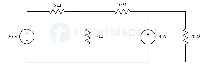
Solution − Let's solve the circuit using Thevenin's theorem to find the response in the 20 Ω resistor.
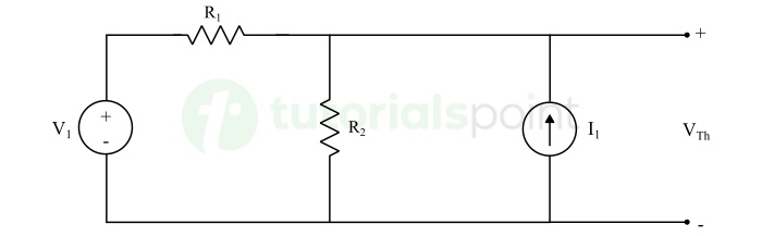
Step 1 − Removing the load resistor, i.e., 20 Ω terminals A and B. Finding the voltage across the open-circuited terminals. This voltage across open terminals will be Thevenin's voltage VTh.
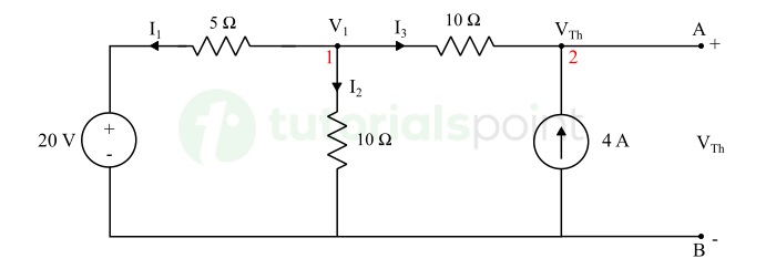
Applying KCL at node 1, we get,
$$\mathrm{I_1 + I_2 + I_3 = 0}$$
$$\mathrm{\frac{V_1 - 20}{5} + \frac{V_1}{10} + \frac{V_1 - V_{Th}}{10} = 0}$$
$$\mathrm{\frac{2V_1 - 40 + V_1 + V_1 - V_{Th}}{10} = 0}$$
$$\mathrm{4V_1 - V_{Th} = 40 \quad \cdots (1)}$$
Applying KCL at node 2, we get,
$$\mathrm{I_3 + 4 = 0}$$
$$\mathrm{\frac{V_1 - V_{Th}}{10} + 4 = 0}$$
$$\mathrm{\Rightarrow V_1 = V_{Th} - 40 \quad \cdots (2)}$$
Substituting the value of V1 from eq. (2) into eq. (1), we get,
$$\mathrm{4(V_{Th} - 40) - V_{Th} = 40}$$
$$\mathrm{\Rightarrow V_{Th} = \frac{200}{3} = 66.67 \: \text{V}}$$
Step 2 − Eliminating all independent sources in the circuit and finding the equivalent resistance across the load terminals. This equivalent resistance will be Thevenin's resistance RTh.
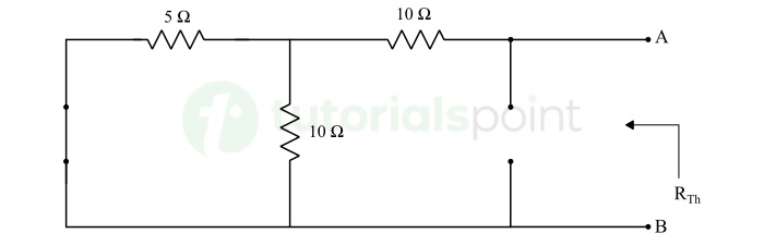
$$\mathrm{R_{Th} = \frac{5 \times 10}{5 + 10} + 10 = \frac{10}{3} + 10}$$
$$\mathrm{\therefore R_{Th} = 13.33 \: \Omega}$$
Step 3 − Constructing the Thevenin's equivalent circuit by connection VTh and RTh in series and connecting the load resistor (20 Ω) across the load terminals A and B.
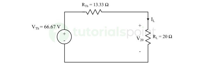
Step 4 − Finally, finding the current through and voltage across the 20 Ω resistor by applying basic circuit laws.
$$\mathrm{I_L = \frac{66.67}{13.33 + 20} = 2 \: \text{A}}$$
$$\mathrm{V_{20} = 2 \times 20 = 40 \: \text{V}}$$
Conclusion
Thevenin's Theorem can be applied to both AC and DC circuits, but note that it can be applied to only those AC circuits that comprise of linear elements like resistors, inductors, and capacitors. In this chapter, we explained the Thevenin's theorem and how it can applied to solve electric circuits. Let's move ahead in the tutorial and learn another important theorem called Norton's theorem.
