- BEEE - Home
- BEEE - Introduction
- Basic Electrical Quantities
- Ohm's Law
- Kirchhoff's Current Law
- Kirchhoff's Voltage Law
- Types of Circuit Elements
- Series Circuit
- Parallel Circuit
- Voltage Division and Voltage Divider
- Current Division and Current Divider
- Star and Delta Connection
- Electric Power and Electrical Energy
- Effects of Electric Current
- Electrical Safety Measures
- DC Circuits and Network Theorems
- Basics of DC Circuits
- Nodal Analysis
- Mesh Analysis
- Thevenin's Theorem
- Norton's Theorem
- Superposition Theorem
- Maximum Power Transfer Theorem
- Source Transformation
- BEEE Useful Resources
- BEEE - Useful Resources
- BEEE - Discussion
Superposition Theorem
In electrical and electronics engineering, Superposition Theorem is an important and elementary tool for electric circuit analysis. This theorem is mainly used in analyzing linear electric circuits that may consist of two or more independent sources like voltage or current sources.
Superposition Theorem is very useful in simplifying and solving complex electric circuits; it also helps in understanding the response of individual sources in the circuit. Read this chapter learn the basics of Superposition Theorem and its application in analyzing electric circuits.
Statement of Superposition Theorem
Superposition Theorem states that in a linear electrical circuit containing two or more independent sources, the output or response (either voltage or current or both) in any circuit element is the algebraic sum of the outputs/responses caused by each independent source acting alone, while all other sources are eliminated or replaced by their internal resistances.
In other words, if two or more voltage or current sources are acting simultaneously in a linear network, the resultant current or voltage in any branch is the algebraic sum of the currents/voltages that would be produced in it, when each source acts alone and all other independent sources are replaced by their internal resistances.
Let's understand the theory of superposition theorem mathematically.
Theory of Superposition Theorem
The step-by-step explanation of superposition theorem in solving electric circuits is given below −
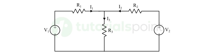
Consider the circuit given below. In this circuit, we have to find the branch currents viz. I1, I2, and I3 by using superposition theorem.
Step 1 − First, we will consider the source V1 alone, and replacing V2 by a short circuit (as it is ideal voltage source).
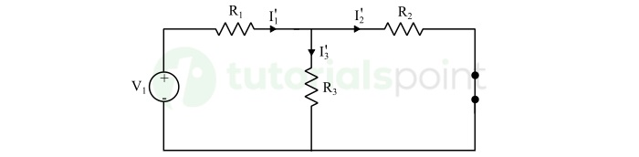
In this case, the currents flowing through branches will be,
$$\mathrm{I_1' = \frac{V_1}{\frac{R_2 R_3}{R_2 + R_3} + R_1}}$$
$$\mathrm{I_2' = I_1' \times \frac{R_3}{R_2 + R_3}}$$
$$\mathrm{I_3' = I_1' - I_2'}$$
These are currents in the circuit when V1 is acting alone, while V2 is deactivated.
Step 2 − Now, we will consider the source V2 alone, and replacing the source V1 by a short circuit.
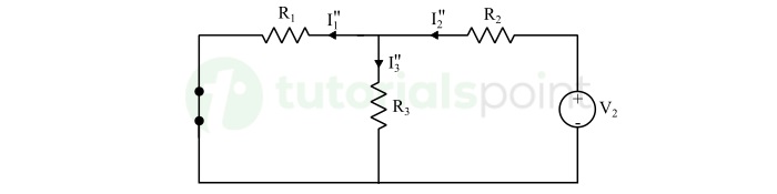
In this case, the currents flowing through branches will be,
$$\mathrm{I_2'' = \frac{V_2}{\frac{R_1 R_3}{R_1 + R_3} + R_2}}$$
$$\mathrm{I_1'' = I_2'' \times \frac{R_3}{R_1 + R_3}}$$
$$\mathrm{I_3'' = I_2'' - I_1''}$$
Step 3 − Finally, applying superposition theorem, we will get,
$$\mathrm{I_1 = I_1' - I_1''}$$
Here $$\mathrm{I_1'}$$ is taken positive as it is in the direction of I1, while I1'' is opposite to the I1.
Similarly,
$$\mathrm{I_2 = I_2'' - I_2'}$$
And,
$$\mathrm{I_3 = I_3' + I_3''}$$
Important Note − During the application of superposition theorem, the direction of currents calculated for each source should be taken care of.
Finally, we can summarize the theory of superposition theorem in following three steps.
Procedure of Superposition Theorem
The following steps can be involved to solve/analyze electric circuits using superposition theorem −
Step 1 − Take only one independent source and deactivate the other independent sources (Voltage source replaced by a short circuit and current source is replaced by an open circuit). Obtain the branch currents with all independent sources acting alone.
Step 2 − Repeat the step 1 until all the sources are considered.
Step 3 − To determine the net branch current using superposition theorem, add the obtained branch currents. If the obtained currents are in the same direction, then add them. If the respective currents are in the opposite directions, then take the direction of original current as reference and subtract the current of opposite direction. This way, calculate the net current in each branch.
After getting a theoretical understanding of superposition theorem, let us learn its application in solving circuits with the help of a solved numerical example.
Circuit Analysis Using Superposition Theorem
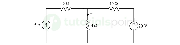
Find the current through 4 Ω resistor in the circuit shown below by using superposition theorem.
Solution − The step-by-step solution for finding the current in 4 Ω resistor in the circuit give above is provided below.
Step 1 − When 5A current source acting alone and 20 V voltage source is removed by short-circuiting −
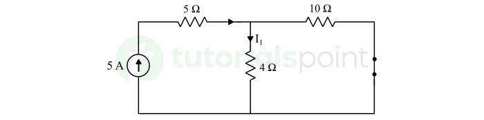
Applying current division rule, we get,
$$\mathrm{I_1 = 5 \times \frac{10}{10 + 4} = \frac{50}{14}}$$
$$\mathrm{\therefore I_1 = \frac{25}{7} \: \text{A}}$$
Step 2 − When 20 V source acting alone and 5 A current source is replaced by open circuit −
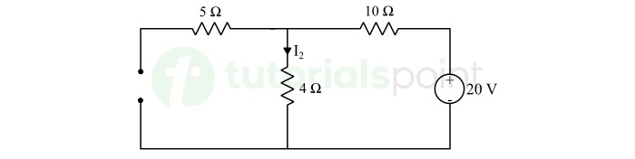
Applying voltage division rule, we get,
$$\mathrm{I_2 = \frac{20}{10 + 4} = \frac{20}{14}}$$
$$\mathrm{\therefore I_2 = \frac{10}{7} \: \text{A}}$$
Step 3 − According to superposition theorem, the total current flowing through the 4 Ω resistor will be,
$$\mathrm{I = I_1 + I_2}$$
As both currents are flowing in the same direction as the total current,
$$\mathrm{I = \frac{25}{7} + \frac{10}{7} = \frac{35}{7} = 5 \: \text{A}}$$
Hence, the current flowing through 4 Ω resistor is 5 A.
Conclusion
In conclusion, superposition theorem is an important tool for electric circuit analysis. It helps electrical and electronics engineers in analyzing complex circuits by breaking them into simple and smaller circuits.
