- BEEE - Home
- BEEE - Introduction
- Basic Electrical Quantities
- Ohm's Law
- Kirchhoff's Current Law
- Kirchhoff's Voltage Law
- Types of Circuit Elements
- Series Circuit
- Parallel Circuit
- Voltage Division and Voltage Divider
- Current Division and Current Divider
- Star and Delta Connection
- Electric Power and Electrical Energy
- Effects of Electric Current
- Electrical Safety Measures
- DC Circuits and Network Theorems
- Basics of DC Circuits
- Nodal Analysis
- Mesh Analysis
- Thevenin's Theorem
- Norton's Theorem
- Superposition Theorem
- Maximum Power Transfer Theorem
- Source Transformation
- BEEE Useful Resources
- BEEE - Useful Resources
- BEEE - Discussion
Mesh Analysis
In electrical and electronics engineering, there is a process called circuit analysis in which we determine unknown electrical quantities like current, voltage, and power in an electric circuit. For this, we have several methods, but the two most fundamental and widely used circuit analysis techniques are as follows −
- Mesh Analysis
- Nodal Analysis
We have discussed Nodal Analysis in the previous chapter. In this chapter, we will learn about Mesh Analysis. Here we will cover the basic introduction and step-by-step procedure of mesh analysis.
What is Mesh Analysis?
Mesh Analysis is a circuit analysis technique used to determine currents flowing in an electric circuit, more specifically in a planner electric circuit. A planner circuit is one that can be drawn without crossing its branches. Mesh Analysis is also known as the Mesh Current Method.
Here are some of the important points to note on mesh analysis −
- It is based on Kirchhoff's Voltage Law (KVL).
- It must be used for circuits having a fewer number of meshes as compared to nodes.
- It must be used in circuits having unknown mesh currents.
What is a Mesh?
The smallest closed loop in an electric circuit is called a mesh. A mesh does not contain any other loop inside it. It is important to note that every mesh in a circuit is a loop, but not every loop is a mesh.
Procedure of Mesh Analysis
The step-by-step procedure of mesh analysis is explained below −
Step 1 − First of all, identify all meshes/smallest independent loops in the circuit.
Step 2 − Assign currents to each mesh, either in clockwise or anti-clockwise direction.
Step 3 − Write KVL equation for each mesh, where voltage drops are taken negative and voltage rises are taken positive.
Step 4 − Solve the simultaneous equations to determine mesh currents.
Step 5 − Utilize these mesh currents to calculate other quantities in the circuit such as branch currents, voltages, powers, etc.
Let us understand the application of mesh analysis in solving electric circuits with the help of an example.
Numerical Example on Mesh Analysis
Determine the voltage drop and the power consumed in the 30 Ω resistor in the circuit shown below.
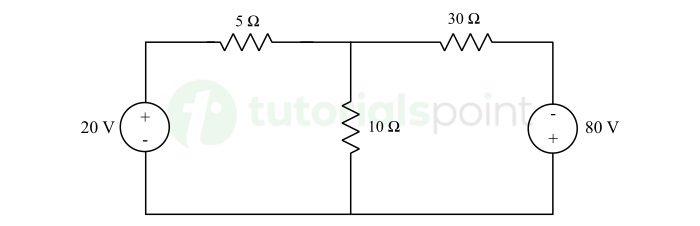
Solution − There are two meshes in the given circuit. Let mesh currents I1 and I2 are flowing in clockwise direction in these meshes as shown in the following figure.
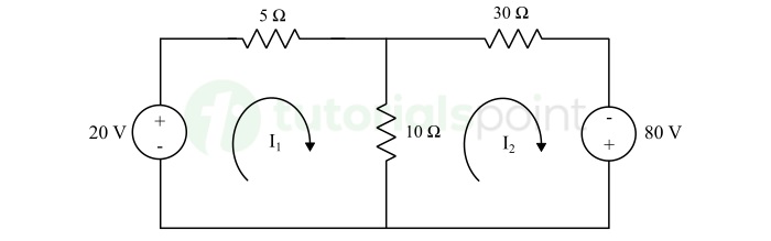
Applying KVL in first loop, we can write,
$$\mathrm{20 - 5 I_1 - 10 (I_1 - I_2) = 0}$$
$$\mathrm{\Rightarrow 20 - 5 I_1 - 10 I_1 + 10 I_2 = 0}$$
$$\mathrm{20 - 15 I_1 + 10 I_2 = 0}$$
Dividing the above equation by 5, we get,
$$\mathrm{4 - 3 I_1 + 2 I_2 = 0}$$
$$\mathrm{\Rightarrow 3 I_1 = 4 + 2 I_2 \quad \cdots (1)}$$
Similarly, applying KVL to the second loop, we get,
$$\mathrm{80 - 10 (I_2 - I_1) - 30 I_2 = 0}$$
$$\mathrm{\Rightarrow 80 - 10 I_2 + 10 I_1 - 30 I_2 = 0}$$
$$\mathrm{\Rightarrow 80 - 40 I_2 + 10 I_1 = 0}$$
$$\mathrm{\Rightarrow I_1 = 4 I_2 - 8 \quad \cdots (2)}$$
Substituting the value of I1 from equation (2) into equation (1), we get,
$$\mathrm{3 (4 I_2 - 8) = 4 + 2 I_2}$$
$$\mathrm{\Rightarrow 12 I_2 - 24 = 4 + 2 I_2}$$
$$\mathrm{I_2 = 2.8 \ \text{A}}$$
Substituting the value of I2 into equation (2), we get,
$$\mathrm{I_1 = 4 \times 2.8 - 8}$$
$$\mathrm{\Rightarrow I_1 = 3.2 \ \text{A}}$$
Now, the voltage drop across 30 Ω resistor in the circuit is,
$$\mathrm{V_{30 \Omega} = 30 \times I_2 = 30 \times 2.8}$$
$$\mathrm{\therefore V_{30 \Omega} = 84 \ \text{V}}$$
The power consumed in the resistor is,
$$\mathrm{P_{30 \Omega} = VI = 84 \times 2.8}$$
$$\mathrm{\therefore P_{30 \Omega} = 235.2 \ \text{W}}$$
Hence, the voltage drop across the 30 Ohm resistor in the circuit is 84 V and the power consumed is 235.2 W.
Conclusion
Mesh analysis is a powerful and widely used technique for analyzing electrical circuits. This technique is based on KVL and provides a step-by-step approach to solve complex circuits easily.
