- BEEE - Home
- BEEE - Introduction
- Basic Electrical Quantities
- Ohm's Law
- Kirchhoff's Current Law
- Kirchhoff's Voltage Law
- Types of Circuit Elements
- Series Circuit
- Parallel Circuit
- Voltage Division and Voltage Divider
- Current Division and Current Divider
- Star and Delta Connection
- Electric Power and Electrical Energy
- Effects of Electric Current
- Electrical Safety Measures
- DC Circuits and Network Theorems
- Basics of DC Circuits
- Nodal Analysis
- Mesh Analysis
- Thevenin's Theorem
- Norton's Theorem
- Superposition Theorem
- Maximum Power Transfer Theorem
- Source Transformation
- BEEE Useful Resources
- BEEE - Useful Resources
- BEEE - Discussion
Nodal Analysis
There are two basic methods that are used for solving any electrical network, and they are −
- Nodal Analysis
- Mesh Analysis
In this chapter, we will cover the Nodal Analysis method in detail. In Nodal analysis, we will consider the node voltages with respect to Ground/reference node in the circuit. Hence, Nodal analysis is also called as Node-Voltage Method. It is one of the most frequently used methods for solving electric circuits.
What is Nodal Analysis?
Nodal Analysis is a circuit analysis technique used to analyze electrical circuits. The main objective of nodal analysis is to determine the voltage at different points called nodes in an electric circuit with respect to a reference point called the ground node.
After determining the node voltages, other parameters like current, power, etc. can be calculated using the Ohm's law. Nodal analysis is mainly used for solving circuits having the following characteristics −
- When the circuit has a number of current sources
- When the circuit consists of a large number of resistors
- When we require a simple method to solve the circuits, etc.
Concepts Related to Nodal Analysis
Let us first get a basic overview of some of the important concepts related nodal analysis −
- Node − A node in an electric circuit is a point where two or more components are connected together.
- Junction − A junction in an electric circuit is a point where three or more elements or branches join each other.
- Node Voltage − Node voltage is the electric potential of a node/junction measured with respect to a ground/reference node.
$$\mathrm{Node \: Voltage = V_{node} - V_{gnd}}$$
Where Vnode is the potential at the node and Vgnd is the potential of the round/reference node.
- Reference / Ground Node − In an electric circuit, a point is selected as the reference/ground node with the following standard assumptions −
- Its voltage is taken to be 0 volts.
- Voltages of all other nodes/junctions are measured with respect to this node.
- This is the node connected to the maximum number of components/branches.
Nodal Analysis Procedure
The step-by-step procedure for solving electric circuits using the nodal analysis is explained below −
Step 1 − Determine all nodes in the circuit and find the number of principal nodes, i.e., nodes with three or more components or branches connected with them.
Step 2 − Select one node as ground/reference node and set it to ground or 0 V potential. Voltages of all other nodes will be measured with respect to this reference node.
Step 3 − Assign voltages to all principal nodes such as $\mathrm{V_1, V_2, V_3}$, etc.
Step 4 − At each principal node, apply KCL to write node equations.
Step 5 − Solve the simultaneous equations using algebra to find the node voltages and other parameters such as current, power, or energy.
Here are some of the key points on nodal analysis −
- Nodal analysis is based on Kirchhoff's Current Law (KCL)
- Always choose a ground/reference node
- Write KCL equations only for principal/non-reference nodes
Mistakes to Avoid in Nodal Analysis
Given below are some of the common mistakes that beginners can make and should avoid −
- Forget to define a ground/reference node
- Mix up directions of branch currents
- Write incorrect potential differences in KCL equations
- Ignore directions of currents provided by current sources
- Not using a consistent sign convention throughout, etc.
Let us now take a numerical example to understand the implementation of nodal analysis in analyzing electric circuit.
Numerical Example
Determine the electric current and power consumed in the 20 Ω resistor in the circuit shown below −
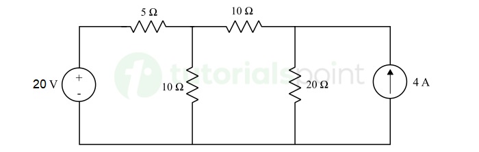
Solution − The given circuit has three nodes marked as 1, 2, and 3 with voltages V1 and V2, where node 3 is chosen as the reference node with 0 V potential as shown in the figure below.
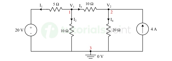
In the above circuit, we also marked assumed currents and their directions.
Applying KCL at node 1, we can write,
$$\mathrm{I_1 + I_2 + I_3 = 0}$$
According to Ohm's law, we get,
$$\mathrm{\frac{V_1 - 20}{5} + \frac{V_1}{10} + \frac{V_1 - V_2}{10} = 0}$$
$$\mathrm{\Rightarrow \frac{2V_1 - 40 + V_1 + V_1 - V_2}{10} = 0}$$
$$\mathrm{\Rightarrow 4V_1 - V_2 = 40 \quad \cdots (1)}$$
Also,
$$\mathrm{V_2 = 4V_1 - 40 \quad \cdots (2)}$$
Applying KCL at node 2, we can write,
$$\mathrm{I_3 + 4 = I_4}$$
According to Ohm's law,
$$\mathrm{\frac{V_1 - V_2}{10} + 4 = \frac{V_2}{20}}$$
$$\mathrm{\Rightarrow \frac{V_1 - V_2 + 40}{10} = \frac{V_2}{20}}$$
$$\mathrm{\Rightarrow 2V_1 - 2V_2 + 80 = V_2}$$
$$\mathrm{\Rightarrow 3V_2 - 2V_1 = 80 \quad \cdots (3)}$$
From equations (2) and (3), we have,
$$\mathrm{3(4V_1 - 40) - 2V_1 = 80}$$
$$\mathrm{\Rightarrow 12V_1 - 120 - 2V_1 = 80}$$
$$\mathrm{10V_1 = 200}$$
$$\mathrm{\therefore V_1 = 20 \: \text{Volts}}$$
Substituting value of V1 in equation 2, we get,
$$\mathrm{V_2 = 4 \times 20 - 40}$$
$$\mathrm{\therefore V_2 = 40 \: \text{Volts}}$$
Hence, the node voltages V1 and V2 as 20 V and 40 V respectively.
Now, the current flowing through the 20 Ω resistor is I4 whose value will be,
$$\mathrm{I_4 = \frac{V_2}{20} = \frac{40}{20} = 2 \: \text{A}}$$
The power consumed by this resistor will be,
$$\mathrm{P = I^2 R = 2^2 \times 20 = 80 \: \text{W}}$$
Hence, the current through 20 Ω resistor is 2 A and the power consumed is 80 W.
Conclusion
In conclusion, Nodal analysis is one of the most widely used circuit analysis method, as it involves the use of basic circuit laws such as KCL and Ohm's law, which are easy to apply in complex circuits.
