- BEEE - Home
- BEEE - Introduction
- Basic Electrical Quantities
- Ohm's Law
- Kirchhoff's Current Law
- Kirchhoff's Voltage Law
- Types of Circuit Elements
- Series Circuit
- Parallel Circuit
- Voltage Division and Voltage Divider
- Current Division and Current Divider
- Star and Delta Connection
- Electric Power and Electrical Energy
- Effects of Electric Current
- Electrical Safety Measures
- DC Circuits and Network Theorems
- Basics of DC Circuits
- Nodal Analysis
- Mesh Analysis
- Thevenin's Theorem
- Norton's Theorem
- Superposition Theorem
- Maximum Power Transfer Theorem
- Source Transformation
- BEEE Useful Resources
- BEEE - Useful Resources
- BEEE - Discussion
Norton's Theorem
Norton's Theorem is similar to Thevenin's Theorem, which we already discussed in the previous chapter. Norton's theorem converts a complex linear two-terminal electric circuit into a simpler two-terminal circuit consisting of a current source with a parallel resistor. In this chapter, we will learn all the fundamental concepts of Norton's Theorem.
Norton's Theorem is an important theorem in electric circuit analysis or network theory. It is primarily used in simplifying complex two-terminal linear electric circuits into an equivalent circuit that can be easily analyzed. Norton's theorem is used when we need to determine the current through or the voltage across a load component connected to a circuit/network.
Statement of Norton's Theorem
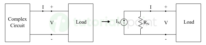
Norton's Theorem states that a linear, bilateral, two-terminal electrical circuit containing components like voltage sources, current sources, resistors, inductors, capacitors, etc. can be replaced by an equivalent circuit which consists of a single current source in parallel with a single resistance, looking from the output/load terminals.
The equivalent circuit is known as Norton's Equivalent Circuit. The single current source is called Norton's Current Source (IN), and the single parallel resistance is called Norton's Resistance (RN).
The following figure graphically represents the statement of Norton's theorem −
Importance of Norton's Theorem in Circuit Analysis
Norton's theorem plays a significant role in circuit analysis, as it does the following −
- It simplifies complex linear circuits.
- It makes current and voltage calculations simpler.
- It simplifies analysis of parallel circuits.
- It is also used for fault analysis in power systems.
- It minimizes mathematical computation in large/complex circuits, etc.
Procedure of Norton's Theorem
The step-by-step procedure for analyzing electric circuits using Norton's theorem is explained below −
Step 1 − First of all, remove the load element from the circuit and mark open terminals as output terminals.
Step 2 − Short-circuit the output terminals and calculate the current flowing through the short-circuit. This will be Norton's current (IN).
Step 3 − Eliminate all independent sources in the circuit (by replacing ideal voltage sources with short circuits and ideal current sources with open circuits). Calculate the equivalent resistance looking from the open output terminals. This will be Norton resistance (RN).
Step 4 − Finally, construct the Norton's equivalent circuit by connecting current source (IN) in parallel with Norton resistance (RN).
Step 5 − At last, reconnect the load resistance (RL) across output terminals and calculate response like current through or voltage across it.
The load current can be directly calculated using the following standard Norton's equation −
$$\mathrm{I_L = I_N \times \frac{R_N}{R_N + R_L}}$$
After getting a theoretical understanding of Norton's theorem, let us understand its implementation in circuit analysis through a solved numerical example.
Circuit Analysis Using Norton's Theorem
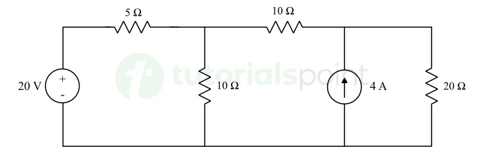
Determine the electric current flowing through and voltage across 20 Ω resistor in the following circuit by using Norton's theorem.
Solution − Finding Norton Current (IN) in the circuit:
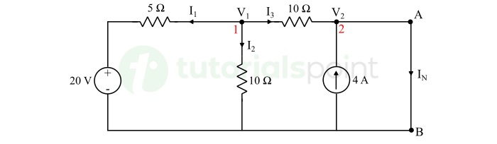
Applying KCL at node (1), we get,
$$\mathrm{I_1 + I_2 + I_3 = 0}$$
$$\mathrm{\Rightarrow \frac{V_1 - 20}{5} + \frac{V_1}{10} + \frac{V_1 - V_2}{10} = 0}$$
$$\mathrm{\Rightarrow 4V_1 - V_2 = 40}$$
$$\mathrm{\Rightarrow V_2 = 4V_1 - 40 \quad \cdots (1)}$$
Applying KCL at node (2), we get,
$$\mathrm{I_3 + 4 = I_N}$$
$$\mathrm{\Rightarrow \frac{V_1 - V_2}{10} + 4 = I_N}$$
$$\mathrm{\Rightarrow V_1 - V_2 + 40 = 10I_N}$$
Substituting the value of V2 from equation (1), we get,
$$\mathrm{\Rightarrow V_1 - (4V_1 - 40) + 40 = 10I_N}$$
$$\mathrm{\Rightarrow I_N = 5 \: \text{A}}$$
Hence, Norton current is 5 A in the given circuit.
Finding Norton Resistance (RN)
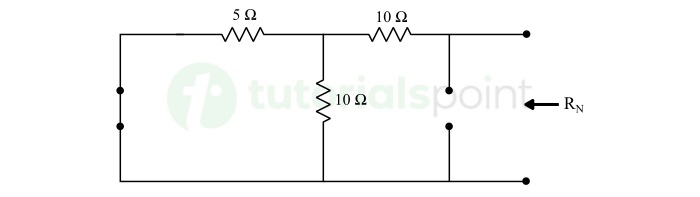
Eliminating ideal voltage and current sources from the circuit. Voltage source is replaced by short circuit and current source is replaced by an open circuit as shown in the above circuit.
$$\mathrm{R_N = \frac{5 \times 10}{5 + 10} + 10}$$
$$\mathrm{\therefore R_N = 13.33 \: \Omega}$$
Hence, the Norton resistance is 13.33 Ω.
Constructing Norton's Equivalent Circuit with Load Reconnected
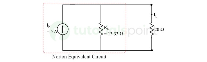
The current flowing through 20 Ω resistor and voltage across will be,
$$\mathrm{I_L = I_N \times \frac{R_N}{R_N + R_L} = 5 \times \frac{13.33}{13.33 + 20}}$$
$$\mathrm{\therefore I_L = 2 \: \text{A}}$$
$$\mathrm{V_L = I_L \times R_L = 2 \times 20}$$
$$\mathrm{\therefore V_L = 40 \: \text{V}}$$
Hence, the current through and voltage across the 20 Ω resistor is 2 A and 40 V respectively.
Conclusion
In conclusion, Norton's Theorem is an important and powerful tool for making electric circuit analysis easier. It simplifies the circuit analysis by converting a complex network into a simple circuit having a single current source with a parallel resistor.
After getting introduction to two fundamental theorems of circuit analysis, let's move ahead in this tutorial to learn another important circuit analysis tool called Superposition Theorem.
