- Antenna Theory - Fundamentals
- Antenna Theory - Basic Parameters
- Antenna Theory - Parameters
- Antenna Theory - Near & Far Fields
- Antenna Theory - Radiation Pattern
- Isotropic Radiation
- Antenna - Beam & Polarization
- Antenna Theory - Beam Width
- Antenna Theory - Reciprocity
- Antenna Theory - Poynting Vector
- Types of Antennas
- Antenna Theory - Types of Antennas
- Antenna Theory - Wire
- Antenna - Half-Wave Dipole
- Antenna - Half-Wave Folded Dipole
- Antenna - Full-Wave Dipole
- Antenna Theory - Short Dipole
- Antenna Theory - Long Wire
- Antenna Theory - V-Antennas
- Inverted V-Antenna
- Antenna Theory - Rhombic
- Antenna Theory - Loop
- Antenna Theory - Helical
- Antenna Theory - Aperture
- Antenna Theory - Horn
- Antenna Theory - Slot
- Antenna Theory - Micro Strip
- Antenna Theory - Lens
- Parabolic Reflector
- Antenna Arrays
- Antenna Theory - Antenna Arrays
- Antenna Theory - Collinear Array
- Antenna Theory - Broad-side Array
- Antenna Theory - End-fire Array
- Antenna Theory - Parasitic Array
- Yagi-Uda Antenna Theory
- Log-periodic Antenna Theory
- Turnstile Antenna Theory
- Wave Propagation
- Antenna - Spectrum & Transmission
- Antenna - Types of Propagation
- Antenna - Lonosphere & its Layers
- Terms in Wave Propagation
- Antenna Theory Useful Resources
- Antenna Theory - Quick Guide
- Antenna Theory - Useful Resources
- Antenna Theory - Discussion
Antenna Theory - Turnstile Antenna
The Turnstile antenna is another type of array antenna. The shape of this array symbolizes the turnstile, which is used at the entrances of few places. This antenna has a wide variety of military applications.
Frequency range
The frequency range in which the turnstile antennas operate is around 30 MHz to 3GHz which belong to the VHF and UHF bands.
Construction & Working of Turnstile Antenna
Two identical half-wave dipoles are placed at right angles to each other and are fed inphase. These dipoles are excited 90 out of phase with each other. Turnstile array can also be termed as crossed dipoles array.
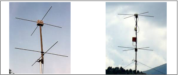
The above images illustrate turnstile antennas.
To provide high directivity, several turnstiles may be stacked along a vertical axis, and are phased as shown in the figure given above. The polarization of these turnstile antennas depend upon their mode of operation.
The pair of such dipoles frequently stacked, is known as BAY. In the figures shown above, two bays are spaced half wavelength (/2) apart and the corresponding elements are fed in phase. The radiation produce by the combination of bays results in better directivity.
Modes of Operation
The following are the modes of operation of a Turnstile antenna.
Normal mode
In Normal mode of operation, the antenna radiates horizontally polarized waves which are perpendicular to its axis.
Axial mode
In Axial mode of operation, the antenna radiates circularly polarized waves along its axis i.e. parallel to its axis.
For circular polarization, the transmitter radiating with right-circular polarization should have a receiver with same right-circular polarization and vice versa. If it is left-circular polarized one, unlike the transmitter, there will be a severe loss of gain.
Super Turnstile Antenna
For a turnstile antenna, the radiation power is 3dB below the maximum radiation of a halfwave dipole radiating the same power. Therefore, to overcome this disadvantage, the Super-turnstile antenna is built.
The simple dipole elements in turnstile are replaced by four flat sheets in Super-turnstile. The design of Super-turnstile array is such that 1 to 8 bays can be constructed on a single mast. The other name for Super-turnstile antenna is the Batwing Antenna.
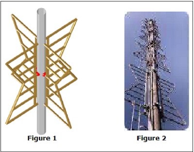
The above images show super-turnstile antenna. Figure 1 shows the arrangement of superturnstile array with the red dots being the feed points. Figure 2 shows the stacked turnstile array used in satellite communications.
Radiation Pattern
The radiation pattern will be similar to the radiation pattern of two super imposed dipoles. Though it is close to omni-directional pattern, it leaves a cloveleaf shaped pattern.
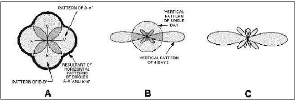
The above figure shows the radiational pattern of a turnstile array. The typical figure-ofeight patterns were combined to produce a nearly circular pattern.
Figure A shows the individual patterns being combined.
Figure B shows the vertical pattern of single bay and also the combined pattern of four bays.
Figure C shows the resultant combined pattern of four bays showing better directivity.
Advantages
The following are the advantages of Turnstile antennas −
High-gain is achieved by stacking
Super-turnstile produces high-gain output
Better directivity is achieved
Disadvantage
The following is the disadvantage of Turnstile antennas −
The radiation power is 3dB below the maximum radiation of a half wave dipole radiating the same power.
Applications
The following are the applications of Turnstile antennas −
Used for VHF communications
Used for FM and TV broadcasting
Used in military communications
Used in satellite communications
