- Antenna Theory - Fundamentals
- Antenna Theory - Basic Parameters
- Antenna Theory - Parameters
- Antenna Theory - Near & Far Fields
- Antenna Theory - Radiation Pattern
- Isotropic Radiation
- Antenna - Beam & Polarization
- Antenna Theory - Beam Width
- Antenna Theory - Reciprocity
- Antenna Theory - Poynting Vector
- Types of Antennas
- Antenna Theory - Types of Antennas
- Antenna Theory - Wire
- Antenna - Half-Wave Dipole
- Antenna - Half-Wave Folded Dipole
- Antenna - Full-Wave Dipole
- Antenna Theory - Short Dipole
- Antenna Theory - Long Wire
- Antenna Theory - V-Antennas
- Inverted V-Antenna
- Antenna Theory - Rhombic
- Antenna Theory - Loop
- Antenna Theory - Helical
- Antenna Theory - Aperture
- Antenna Theory - Horn
- Antenna Theory - Slot
- Antenna Theory - Micro Strip
- Antenna Theory - Lens
- Parabolic Reflector
- Antenna Arrays
- Antenna Theory - Antenna Arrays
- Antenna Theory - Collinear Array
- Antenna Theory - Broad-side Array
- Antenna Theory - End-fire Array
- Antenna Theory - Parasitic Array
- Yagi-Uda Antenna Theory
- Log-periodic Antenna Theory
- Turnstile Antenna Theory
- Wave Propagation
- Antenna - Spectrum & Transmission
- Antenna - Types of Propagation
- Antenna - Lonosphere & its Layers
- Terms in Wave Propagation
- Antenna Theory Useful Resources
- Antenna Theory - Quick Guide
- Antenna Theory - Useful Resources
- Antenna Theory - Discussion
Antenna Theory - Parasitic Array
The antenna arrays as seen above, are used for the improvement of gain and directivity.
A parasitic element is an element, which depends on others feed. It does not have its own feed. Hence, in this type of arrays we employ such elements, which help in increasing the radiation indirectly.
These parasitic elements are not directly connected to the feed.
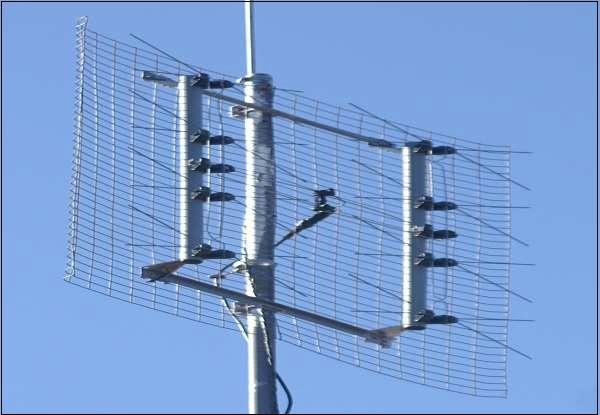
The above image shows an example of a parasitic array. The mesh structure seen in the picture, is nothing but a set of reflectors. These reflectors are not electrically connected. They increase the signal strength by increasing the directivity of the beam.
Construction & Working of Parasitic Array
Let us look at the important parts of a Parasitic array and how they work.
The main parts are −
- Driven element
- Parasitic elements
- Reflector
- Director
- Boom
Driven element
The antennas radiate individually and while in array, the radiation of all the elements sum up to form the radiation beam. All the elements of the array need not be connected to the feed. The dipole that is connected to the feed is known as a driven element.
Parasitic Elements
The elements, which are added do not possess an electrical connection between them to the driven element or the feed. They are positioned so that they lie in the induction field of the driven element. Hence, they are known as parasitic elements.
Reflector
If one of the parasitic element, which is 5% longer than driven element, is placed close to the driven element is longer, then it acts as a concave mirror, which reflects the energy in the direction of the radiation pattern rather than its own direction and hence is known as a reflector.
Director
A parasitic element, which is 5% shorter than the driven element, from which it receives energy, tends to increase radiation in its own direction and therefore, behaves like convergent convex lens. This element is called as a director. A number of directors are placed to increase the directivity.
Boom
The element on which all these are placed is callled a boom. It is a non-metallic structure which provides insulation, so that there will not be any short circuit between the other elements of the array.
These are all the main elements, which contribute the radiation. This can be better understood with the help of a diagram
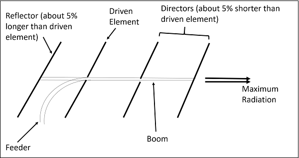
The image shown above is that of a parasitic array, which shows the parts of parsitic array such as the driven element, the directors and the reflector. The feed is given through the feeder.
The arrays are used at frequencies ranging from 2MHz to several GHz. These are especially used to get high directivity, and better forward gain with a uni-directional. The most common example of this type of array is the Yagi-Uda antenna. Quad antenna may also be quoted as another example.
