- Antenna Theory - Fundamentals
- Antenna Theory - Basic Parameters
- Antenna Theory - Parameters
- Antenna Theory - Near & Far Fields
- Antenna Theory - Radiation Pattern
- Isotropic Radiation
- Antenna - Beam & Polarization
- Antenna Theory - Beam Width
- Antenna Theory - Reciprocity
- Antenna Theory - Poynting Vector
- Types of Antennas
- Antenna Theory - Types of Antennas
- Antenna Theory - Wire
- Antenna - Half-Wave Dipole
- Antenna - Half-Wave Folded Dipole
- Antenna - Full-Wave Dipole
- Antenna Theory - Short Dipole
- Antenna Theory - Long Wire
- Antenna Theory - V-Antennas
- Inverted V-Antenna
- Antenna Theory - Rhombic
- Antenna Theory - Loop
- Antenna Theory - Helical
- Antenna Theory - Aperture
- Antenna Theory - Horn
- Antenna Theory - Slot
- Antenna Theory - Micro Strip
- Antenna Theory - Lens
- Parabolic Reflector
- Antenna Arrays
- Antenna Theory - Antenna Arrays
- Antenna Theory - Collinear Array
- Antenna Theory - Broad-side Array
- Antenna Theory - End-fire Array
- Antenna Theory - Parasitic Array
- Yagi-Uda Antenna Theory
- Log-periodic Antenna Theory
- Turnstile Antenna Theory
- Wave Propagation
- Antenna - Spectrum & Transmission
- Antenna - Types of Propagation
- Antenna - Lonosphere & its Layers
- Terms in Wave Propagation
- Antenna Theory Useful Resources
- Antenna Theory - Quick Guide
- Antenna Theory - Useful Resources
- Antenna Theory - Discussion
Antenna Theory - Radiation Pattern
Radiation is the term used to represent the emission or reception of wave front at the antenna, specifying its strength. In any illustration, the sketch drawn to represent the radiation of an antenna is its radiation pattern. One can simply understand the function and directivity of an antenna by having a look at its radiation pattern.
The power when radiated from the antenna has its effect in the near and far field regions.
Graphically, radiation can be plotted as a function of angular position and radial distance from the antenna.
This is a mathematical function of radiation properties of the antenna represented as a function of spherical co-ordinates, E (, ) and H (, ).
Radiation Pattern
The energy radiated by an antenna is represented by the Radiation pattern of the antenna. Radiation Patterns are diagrammatical representations of the distribution of radiated energy into space, as a function of direction.
Let us look at the pattern of energy radiation.
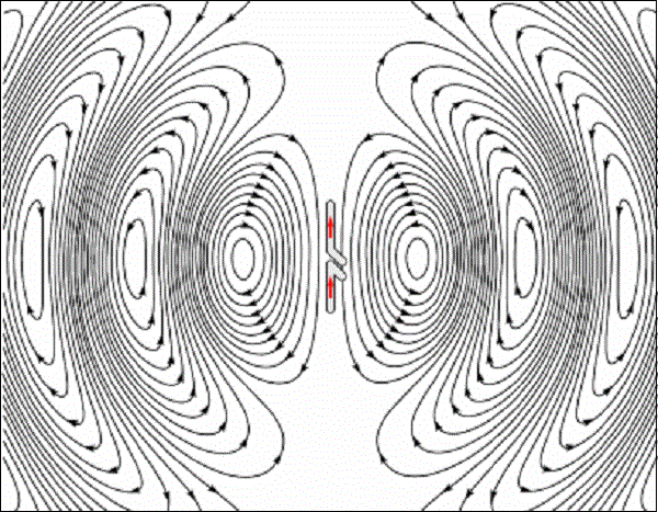
The figure given above shows radiation pattern of a dipole antenna. The energy being radiated is represented by the patterns drawn in a particular direction. The arrows represent directions of radiation.
The radiation patterns can be field patterns or power patterns.
The field patterns are plotted as a function of electric and magnetic fields. They are plotted on logarithmic scale.
The power patterns are plotted as a function of square of the magnitude of electric and magnetic fields. They are plotted on logarithmic or commonly on dB scale.
Radiation Pattern in 3D
The radiation pattern is a three-dimensional figure and represented in spherical coordinates (r, , ) assuming its origin at the center of spherical coordinate system. It looks like the following figure −
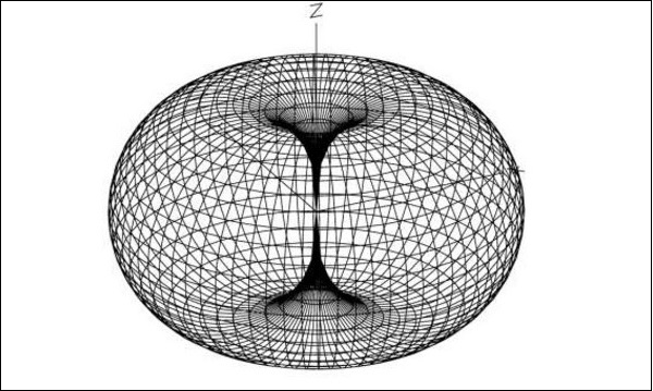
The given figure is a three dimensional radiation pattern for an Omni directional pattern. This clearly indicates the three co-ordinates (x, y, z).
Radiation Pattern in 2D
Two-dimensional pattern can be obtained from three-dimensional pattern by dividing it into horizontal and vertical planes. These resultant patterns are known as Horizontal pattern and Vertical pattern respectively.
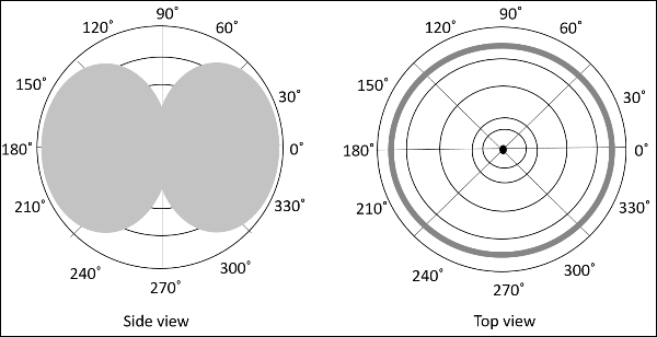
The figures show the Omni directional radiation pattern in H and V planes as explained above. H-plane represents the Horizontal pattern, whereas V-plane represents the Vertical pattern.
Lobe Formation
In the representation of radiation pattern, we often come across different shapes, which indicate the major and minor radiation areas, by which the radiation efficiency of the antenna is known.
To have a better understanding, consider the following figure, which represents the radiation pattern of a dipole antenna.
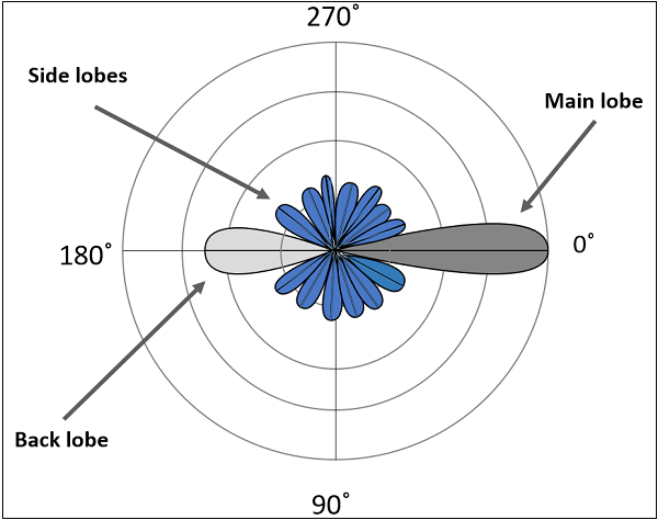
Here, the radiation pattern has main lobe, side lobes and back lobe.
The major part of the radiated field, which covers a larger area, is the main lobe or major lobe. This is the portion where maximum radiated energy exists. The direction of this lobe indicates the directivity of the antenna.
The other parts of the pattern where the radiation is distributed side wards are known as side lobes or minor lobes. These are the areas where the power is wasted.
There is other lobe, which is exactly opposite to the direction of main lobe. It is known as back lobe, which is also a minor lobe. A considerable amount of energy is wasted even here.
Example
If the antennas used in radar systems produce side lobes, target tracing becomes very difficult. This is because, false targets are indicated by these side lobes. It is messy to trace out the real ones and to identify the fake ones. Hence, elimination of these side lobes is must, in order to improve the performance and save the energy.
Remedy
The radiated energy, which is being wasted in such forms needs to be utilized. If these minor lobes are eliminated and this energy is diverted into one direction (that is towards the major lobe), then the directivity of the antenna gets increased which leads to antennas better performance.
Types of Radiation patterns
The common types of Radiation patterns are −
Omni-directional pattern (also called non-directional pattern): The pattern usually has a doughnut shape in three-dimensional view. However, in two-dimensional view, it forms a figure-of-eight pattern.
Pencil-beam pattern − The beam has a sharp directional pencil shaped pattern.
Fan-beam pattern − The beam has a fan-shaped pattern.
Shaped beam pattern − The beam, which is non-uniform and patternless is known as shaped beam.
A referential point for all these types of radiation is the isotropic radiation. It is important to consider the isotropic radiation even though it is impractical.
