- Antenna Theory - Fundamentals
- Antenna Theory - Basic Parameters
- Antenna Theory - Parameters
- Antenna Theory - Near & Far Fields
- Antenna Theory - Radiation Pattern
- Isotropic Radiation
- Antenna - Beam & Polarization
- Antenna Theory - Beam Width
- Antenna Theory - Reciprocity
- Antenna Theory - Poynting Vector
- Types of Antennas
- Antenna Theory - Types of Antennas
- Antenna Theory - Wire
- Antenna - Half-Wave Dipole
- Antenna - Half-Wave Folded Dipole
- Antenna - Full-Wave Dipole
- Antenna Theory - Short Dipole
- Antenna Theory - Long Wire
- Antenna Theory - V-Antennas
- Inverted V-Antenna
- Antenna Theory - Rhombic
- Antenna Theory - Loop
- Antenna Theory - Helical
- Antenna Theory - Aperture
- Antenna Theory - Horn
- Antenna Theory - Slot
- Antenna Theory - Micro Strip
- Antenna Theory - Lens
- Parabolic Reflector
- Antenna Arrays
- Antenna Theory - Antenna Arrays
- Antenna Theory - Collinear Array
- Antenna Theory - Broad-side Array
- Antenna Theory - End-fire Array
- Antenna Theory - Parasitic Array
- Yagi-Uda Antenna Theory
- Log-periodic Antenna Theory
- Turnstile Antenna Theory
- Wave Propagation
- Antenna - Spectrum & Transmission
- Antenna - Types of Propagation
- Antenna - Lonosphere & its Layers
- Terms in Wave Propagation
- Antenna Theory Useful Resources
- Antenna Theory - Quick Guide
- Antenna Theory - Useful Resources
- Antenna Theory - Discussion
Antenna Theory - End-fire Array
The physical arrangement of end-fire array is same as that of the broad side array. The magnitude of currents in each element is same, but there is a phase difference between these currents. This induction of energy differs in each element, which can be understood by the following diagram.
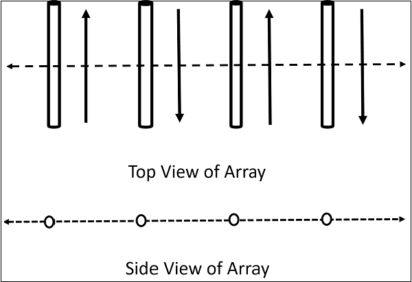
The above figure shows the end-fire array in top and side views respectively.
There is no radiation in the right angles to the plane of the array because of cancellation. The first and third elements are fed out of phase and therefore cancel each others radiation. Similarly, second and fourth are fed out of phase, to get cancelled.
The usual dipole spacing will be /4 or 3/4. This arrangement not only helps to avoid the radiation perpendicular to the antenna plane, but also helps the radiated energy get diverted to the direction of radiation of the whole array. Hence, the minor lobes are avoided and the directivity is increased. The beam becomes narrower with the increased elements.
Radiation Pattern
The Radiation pattern of end-fire array is uni-directional. A major lobe occurs at one end, where maximum radiation is present, while the minor lobes represent the losses.
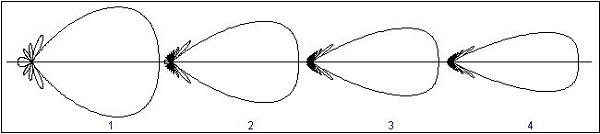
The figure explains the radiation pattern of an end-fire array. Figure 1 is the radiation pattern for a single array, while figures 2, 3, and 4 represent the radiation pattern for multiple arrays.
End-fire Array Vs Broad Side Array
We have studied both the arrays. Let us try to compare the end-fire and broad side arrays, along with their characteristics.
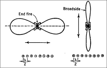
The figure illustrates the radiation pattern of end-fire array and broad side array.
Both, the end fire array and broad side array, are linear and are resonant, as they consist of resonant elements.
Due to resonance, both the arrays display narrower beam and high directivity.
Both of these arrays are used in transmission purposes.
Neither of them is used for reception, because the necessity of covering a range of frequencies is needed for any kind of reception.
