- Analog Communication - Home
- Introduction
- Modulation
- Amplitude Modulation
- Numerical Problems 1
- AM Modulators
- AM Demodulators
- DSBSC Modulation
- DSBSC Modulators
- DSBSC Demodulators
- SSBSC Modulation
- SSBSC Modulators
- SSBSC Demodulator
- VSBSC Modulation
- Angle Modulation
- Numerical Problems 2
- FM Modulators
- FM Demodulators
- Multiplexing
- Noise
- SNR Calculations
- Transmitters
- Receivers
- Sampling
- Pulse Modulation
- Transducers
Analog Communication - Transmitters
The antenna present at the end of transmitter section, transmits the modulated wave. In this chapter, let us discuss about AM and FM transmitters.
AM Transmitter
AM transmitter takes the audio signal as an input and delivers amplitude modulated wave to the antenna as an output to be transmitted. The block diagram of AM transmitter is shown in the following figure.
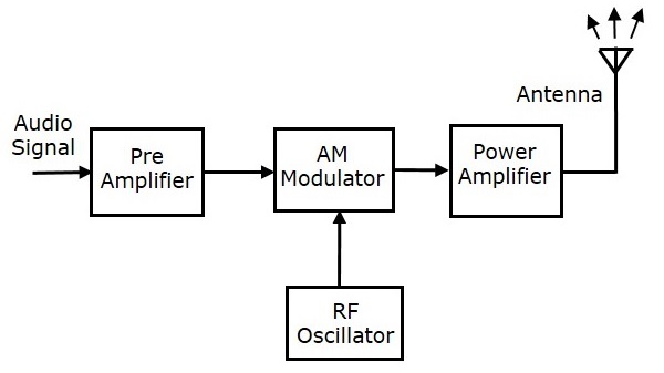
The working of AM transmitter can be explained as follows.
The audio signal from the output of the microphone is sent to the pre-amplifier, which boosts the level of the modulating signal.
The RF oscillator generates the carrier signal.
Both the modulating and the carrier signal is sent to AM modulator.
Power amplifier is used to increase the power levels of AM wave. This wave is finally passed to the antenna to be transmitted.
FM Transmitter
FM transmitter is the whole unit, which takes the audio signal as an input and delivers FM wave to the antenna as an output to be transmitted. The block diagram of FM transmitter is shown in the following figure.
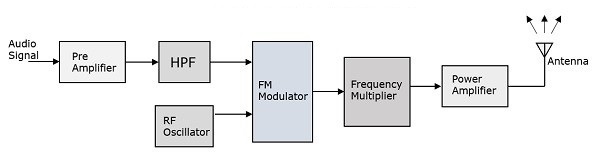
The working of FM transmitter can be explained as follows.
The audio signal from the output of the microphone is sent to the pre-amplifier, which boosts the level of the modulating signal.
This signal is then passed to high pass filter, which acts as a pre-emphasis network to filter out the noise and improve the signal to noise ratio.
This signal is further passed to the FM modulator circuit.
The oscillator circuit generates a high frequency carrier, which is sent to the modulator along with the modulating signal.
Several stages of frequency multiplier are used to increase the operating frequency. Even then, the power of the signal is not enough to transmit. Hence, a RF power amplifier is used at the end to increase the power of the modulated signal. This FM modulated output is finally passed to the antenna to be transmitted.
