- Analog Communication - Home
- Introduction
- Modulation
- Amplitude Modulation
- Numerical Problems 1
- AM Modulators
- AM Demodulators
- DSBSC Modulation
- DSBSC Modulators
- DSBSC Demodulators
- SSBSC Modulation
- SSBSC Modulators
- SSBSC Demodulator
- VSBSC Modulation
- Angle Modulation
- Numerical Problems 2
- FM Modulators
- FM Demodulators
- Multiplexing
- Noise
- SNR Calculations
- Transmitters
- Receivers
- Sampling
- Pulse Modulation
- Transducers
Analog Communication - FM Modulators
In this chapter, let us discuss about the modulators which generate NBFM and WBFM waves. First, let us discuss about the generation of NBFM.
Generation of NBFM
We know that the standard equation of FM wave is
$$s\left ( t \right )=A_c \cos\left ( 2 \pi f_ct+2 \pi k_f\int m\left ( t \right ) dt\right )$$
$\Rightarrow s\left ( t \right )=A_c \cos\left ( 2 \pi f_ct \right ) \cos\left ( 2 \pi k_f\int m\left ( t \right )dt \right )-$
$A_c \sin\left ( 2 \pi f_ct \right ) \sin\left ( 2 \pi k_f\int m\left ( t \right )dt \right )$
For NBFM,
$$\left | 2 \pi k_f\int m\left ( t \right )dt \right |
We know that $\cos \theta \approx 1$ and $\sin \theta \approx 1$ when $\theta$ is very small.
By using the above relations, we will get the NBFM equation as
$$s\left ( t \right )=A_c \cos\left ( 2 \pi f_ct \right )-A_c \sin\left ( 2 \pi f_ct \right )2 \pi k_f\int m\left ( t \right )dt$$
The block diagram of NBFM modulator is shown in the following figure.
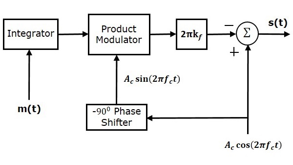
Here, the integrator is used to integrate the modulating signal $m\left (t \right )$. The carrier signal $A_c \cos \left ( 2 \pi f_ct \right )$ is the phase shifted by $-90^0$ to get $A_c \sin \left ( 2 \pi f_ct \right )$ with the help of $-90^0$ phase shifter. The product modulator has two inputs $\int m\left ( t \right )dt$ and $A_c \sin \left ( 2 \pi f_ct \right )$. It produces an output, which is the product of these two inputs.
This is further multiplied with $2 \pi k_f$ by placing a block $2 \pi k_f$ in the forward path. The summer block has two inputs, which are nothing but the two terms of NBFM equation. Positive and negative signs are assigned for the carrier signal and the other term at the input of the summer block. Finally, the summer block produces NBFM wave.
Generation of WBFM
The following two methods generate WBFM wave.
- Direct method
- Indirect method
Direct Method
This method is called as the Direct Method because we are generating a wide band FM wave directly. In this method, Voltage Controlled Oscillator (VCO) is used to generate WBFM. VCO produces an output signal, whose frequency is proportional to the input signal voltage. This is similar to the definition of FM wave. The block diagram of the generation of WBFM wave is shown in the following figure.
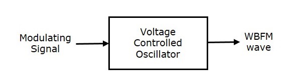
Here, the modulating signal $m\left (t \right )$ is applied as an input of Voltage Controlled Oscillator (VCO). VCO produces an output, which is nothing but the WBFM.
$$f_i \: \alpha \: m\left ( t \right )$$
$$\Rightarrow f_i=f_c+k_fm\left ( t \right )$$
Where,
$f_i$ is the instantaneous frequency of WBFM wave.
Indirect Method
This method is called as Indirect Method because we are generating a wide band FM wave indirectly. This means, first we will generate NBFM wave and then with the help of frequency multipliers we will get WBFM wave. The block diagram of generation of WBFM wave is shown in the following figure.
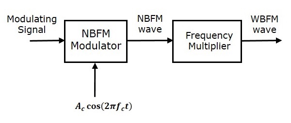
This block diagram contains mainly two stages. In the first stage, the NBFM wave will be generated using NBFM modulator. We have seen the block diagram of NBFM modulator at the beginning of this chapter. We know that the modulation index of NBFM wave is less than one. Hence, in order to get the required modulation index (greater than one) of FM wave, choose the frequency multiplier value properly.
Frequency multiplier is a non-linear device, which produces an output signal whose frequency is n times the input signal frequency. Where, n is the multiplication factor.
If NBFM wave whose modulation index $\beta$ is less than 1 is applied as the input of frequency multiplier, then the frequency multiplier produces an output signal, whose modulation index is n times $\beta$ and the frequency also n times the frequency of WBFM wave.
Sometimes, we may require multiple stages of frequency multiplier and mixers in order to increase the frequency deviation and modulation index of FM wave.
