- Analog Communication - Home
- Introduction
- Modulation
- Amplitude Modulation
- Numerical Problems 1
- AM Modulators
- AM Demodulators
- DSBSC Modulation
- DSBSC Modulators
- DSBSC Demodulators
- SSBSC Modulation
- SSBSC Modulators
- SSBSC Demodulator
- VSBSC Modulation
- Angle Modulation
- Numerical Problems 2
- FM Modulators
- FM Demodulators
- Multiplexing
- Noise
- SNR Calculations
- Transmitters
- Receivers
- Sampling
- Pulse Modulation
- Transducers
Analog Communication - AM Modulators
In this chapter, let us discuss about the modulators, which generate amplitude modulated wave. The following two modulators generate AM wave.
- Square law modulator
- Switching modulator
Square Law Modulator
Following is the block diagram of the square law modulator
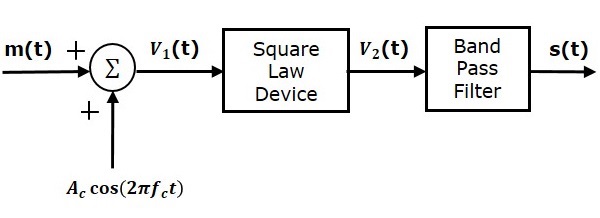
Let the modulating and carrier signals be denoted as $m\left ( t \right )$ and $A\cos\left ( 2\pi f_ct\right )$ respectively. These two signals are applied as inputs to the summer (adder) block. This summer block produces an output, which is the addition of the modulating and the carrier signal. Mathematically, we can write it as
$$V_1t=m\left ( t \right )+A_c\cos\left ( 2 \pi f_ct \right )$$
This signal $V_1t$ is applied as an input to a nonlinear device like diode. The characteristics of the diode are closely related to square law.
$V_2t=k_1V_1\left ( t \right )+k_2V_1^2\left ( t \right )$(Equation 1)
Where, $k_1$ and $k_2$ are constants.
Substitute $V_1\left (t \right )$ in Equation 1
$$V_2\left (t\right ) = k_1\left [ m\left ( t \right ) + A_c \cos \left ( 2 \pi f_ct \right ) \right ] + k_2\left [ m\left ( t \right ) + A_c \cos\left ( 2 \pi f_ct \right ) \right ]^2$$
$\Rightarrow V_2\left (t\right ) = k_1 m\left ( t \right ) +k_1 A_c \cos \left ( 2 \pi f_ct \right ) +k_2 m^2\left ( t \right ) +$
$ k_2A_c^2 \cos^2\left ( 2 \pi f_ct \right )+2k_2m\left ( t \right )A_c \cos\left ( 2 \pi f_ct \right )$
$\Rightarrow V_2\left (t\right ) = k_1 m\left ( t \right ) +k_2 m^2\left ( t \right ) +k_2 A^2_c \cos^2 \left ( 2 \pi f_ct \right ) +$
$k_1A_c\left [ 1+\left ( \frac{2k_2}{k_1} \right )m\left ( t \right ) \right ] \cos\left ( 2 \pi f_ct \right )$
The last term of the above equation represents the desired AM wave and the first three terms of the above equation are unwanted. So, with the help of band pass filter, we can pass only AM wave and eliminate the first three terms.
Therefore, the output of square law modulator is
$$s\left ( t \right )=k_1A_c\left [1+\left ( \frac{2k_2}{k_1} \right ) m\left ( t \right ) \right ] \cos\left ( 2 \pi f_ct \right )$$
The standard equation of AM wave is
$$s\left ( t \right )=A_c\left [ 1+k_am\left ( t \right ) \right ] \cos \left (2 \pi f_ct \right )$$
Where, $K_a$ is the amplitude sensitivity
By comparing the output of the square law modulator with the standard equation of AM wave, we will get the scaling factor as $k_1$ and the amplitude sensitivity $k_a$ as $\frac{2k_2}{k1}$.
Switching Modulator
Following is the block diagram of switching modulator.
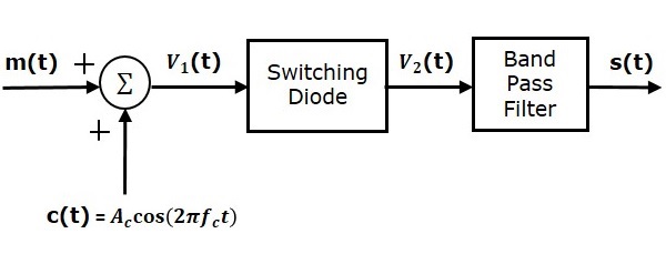
Switching modulator is similar to the square law modulator. The only difference is that in the square law modulator, the diode is operated in a non-linear mode, whereas, in the switching modulator, the diode has to operate as an ideal switch.
Let the modulating and carrier signals be denoted as $m\left ( t \right )$ and $c\left ( t \right )= A_c \cos\left ( 2\pi f_ct \right )$ respectively. These two signals are applied as inputs to the summer (adder) block. Summer block produces an output, which is the addition of modulating and carrier signals. Mathematically, we can write it as
$$V_1\left ( t \right )=m\left ( t \right )+c\left ( t \right )= m\left ( t \right )+A_c \cos\left ( 2 \pi f_ct \right )$$
This signal $V_1\left ( t \right )$ is applied as an input of diode. Assume, the magnitude of the modulating signal is very small when compared to the amplitude of carrier signal $A_c$. So, the diodes ON and OFF action is controlled by carrier signal $c\left ( t \right )$. This means, the diode will be forward biased when $c\left ( t \right )> 0$ and it will be reverse biased when $c\left ( t \right )
Therefore, the output of the diode is
$$V_2 \left ( t \right )=\left\{\begin{matrix} V_1\left ( t \right )& if &c\left ( t \right )>0 \\ 0& if & c\left ( t \right )
We can approximate this as
$V_2\left ( t \right ) = V_1\left ( t \right )x\left ( t \right )$(Equation 2)
Where, $x\left ( t \right )$ is a periodic pulse train with time period $T=\frac{1}{f_c}$
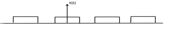
The Fourier series representation of this periodic pulse train is
$$x\left ( t \right )=\frac{1}{2}+\frac{2}{\pi }\sum_{n=1}^{\infty}\frac{\left ( -1 \right )^n-1}{2n-1} \cos\left (2 \pi \left ( 2n-1 \right ) f_ct \right )$$
$$\Rightarrow x\left ( t \right )=\frac{1}{2}+\frac{2}{\pi} \cos\left ( 2 \pi f_ct \right )-\frac{2}{3\pi } \cos\left ( 6 \pi f_ct \right ) +....$$
Substitute, $V_1\left ( t \right )$ and $x\left ( t \right )$ values in Equation 2.
$V_2\left ( t \right )=\left [ m\left ( t \right )+A_c \cos\left ( 2 \pi f_ct \right ) \right ] \left [ \frac{1}{2} + \frac{2}{\pi} \cos \left ( 2 \pi f_ct \right )-\frac{2}{3\pi} \cos\left ( 6 \pi f_ct \right )+.....\right ]$
$V_2\left ( t \right )=\frac{m\left ( t \right )}{2}+\frac{A_c}{2} \cos\left ( 2 \pi f_ct \right )+\frac{2m\left ( t \right )}{\pi} \cos\left ( 2 \pi f_ct \right ) +\frac{2A_c}{\pi} \cos^2\left ( 2 \pi f_ct \right )-$
$\frac{2m\left ( t \right )}{3\pi} \cos\left ( 6 \pi f_ct \right )-\frac{2A_c}{3\pi}\cos \left ( 2 \pi f_ct \right ) \cos\left ( 6 \pi f_ct \right )+..... $
$V_2\left ( t \right )=\frac{A_c}{2}\left ( 1+\left ( \frac{4}{\pi A_c} \right )m\left ( t \right ) \right ) \cos\left ( 2 \pi f_ct \right ) + \frac{m\left ( t \right )}{2}+\frac{2A_c}{\pi} \cos^2\left ( 2 \pi f_ct \right )-$
$\frac{2m\left ( t \right )}{3 \pi} \cos\left ( 6 \pi f_ct \right )-\frac{2A_c}{3\pi} \cos\left ( 2 \pi f_ct \right ) \cos\left ( 6 \pi f_ct \right )+.....$
The 1st term of the above equation represents the desired AM wave and the remaining terms are unwanted terms. Thus, with the help of band pass filter, we can pass only AM wave and eliminate the remaining terms.
Therefore, the output of switching modulator is
$$s\left ( t \right )=\frac{A_c}{2}\left ( 1+\left ( \frac{4}{\pi A_c} \right ) m\left ( t \right )\right ) \cos\left ( 2 \pi f_ct \right )$$
We know the standard equation of AM wave is
$$s\left ( t \right )=A_c\left [ 1+k_am\left ( t \right ) \right ] \cos\left ( 2 \pi f_ct \right )$$
Where, $k_a$ is the amplitude sensitivity.
By comparing the output of the switching modulator with the standard equation of AM wave, we will get the scaling factor as 0.5 and amplitude sensitivity $k_a$ as $\frac{4}{\pi A_c}$ .
