- Analog Communication - Home
- Introduction
- Modulation
- Amplitude Modulation
- Numerical Problems 1
- AM Modulators
- AM Demodulators
- DSBSC Modulation
- DSBSC Modulators
- DSBSC Demodulators
- SSBSC Modulation
- SSBSC Modulators
- SSBSC Demodulator
- VSBSC Modulation
- Angle Modulation
- Numerical Problems 2
- FM Modulators
- FM Demodulators
- Multiplexing
- Noise
- SNR Calculations
- Transmitters
- Receivers
- Sampling
- Pulse Modulation
- Transducers
Analog Communication - Receivers
The antenna present at the beginning of the receiver section, receives the modulated wave. First let us discuss the requirements of a receiver.
Requirements of a Receiver
AM receiver receives AM wave and demodulates it by using the envelope detector. Similarly, FM receiver receives FM wave and demodulates it by using the Frequency Discrimination method. Following are the requirements of both AM and FM receiver.
It should be cost-effective.
It should receive the corresponding modulated waves.
The receiver should be able to tune and amplify the desired station.
It should have an ability to reject the unwanted stations.
Demodulation has to be done to all the station signals, irrespective of the carrier signal frequency.
For these requirements to be fulfilled, the tuner circuit and the mixer circuit should be very effective. The procedure of RF mixing is an interesting phenomenon.
RF Mixing
The RF mixing unit develops an Intermediate Frequency (IF) to which any received signal is converted, so as to process the signal effectively.
RF Mixer is an important stage in the receiver. Two signals of different frequencies are taken where one signal level affects the level of the other signal, to produce the resultant mixed output. The input signals and the resultant mixer output is illustrated in the following figures.
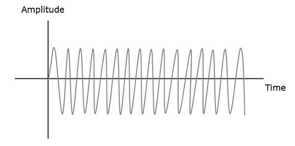
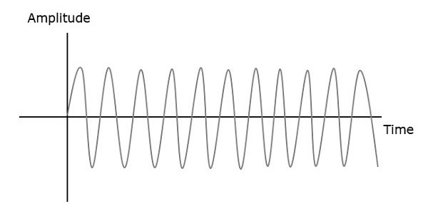
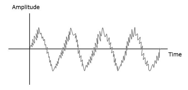
Let the first and second signal frequencies be $f_1$ and $f_2$. If these two signals are applied as inputs of RF mixer, then it produces an output signal, having frequencies of $f_1+f_2$ and $f_1-f_2$.
If this is observed in the frequency domain, the pattern looks like the following figure.
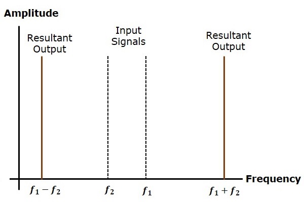
In this case, $f_1$ is greater than $f_2$. So, the resultant output has frequencies $f_1+f_2$ and $f_1-f_2$. Similarly, if $f_2$ is greater than $f_1$, then the resultant output will have the frequencies $f_1+f_2$ and $f_1-f_2$.
AM Receiver
The AM super heterodyne receiver takes the amplitude modulated wave as an input and produces the original audio signal as an output. Selectivity is the ability of selecting a particular signal, while rejecting the others. Sensitivity is the capacity of detecting RF signal and demodulating it, while at the lowest power level.
Radio amateurs are the initial radio receivers. However, they have drawbacks such as poor sensitivity and selectivity. To overcome these drawbacks, super heterodyne receiver was invented. The block diagram of AM receiver is shown in the following figure.
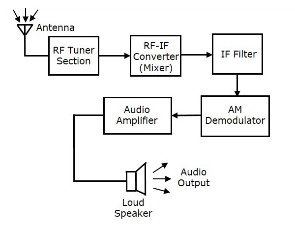
RF Tuner Section
The amplitude modulated wave received by the antenna is first passed to the tuner circuit through a transformer. The tuner circuit is nothing but a LC circuit, which is also called as resonant or tank circuit. It selects the frequency, desired by the AM receiver. It also tunes the local oscillator and the RF filter at the same time.
RF Mixer
The signal from the tuner output is sent to the RF-IF converter, which acts as a mixer. It has a local oscillator, which produces a constant frequency. The mixing process is done here, having the received signal as one input and the local oscillator frequency as the other input. The resultant output is a mixture of two frequencies $\left [ \left ( f_1+f_2 \right ) , \left ( f_1-f_2 \right )\right ]$ produced by the mixer, which is called as the Intermediate Frequency (IF).
The production of IF helps in the demodulation of any station signal having any carrier frequency. Hence, all signals are translated to a fixed carrier frequency for adequate selectivity.
IF Filter
Intermediate frequency filter is a band pass filter, which passes the desired frequency. It eliminates all other unwanted frequency components present in it. This is the advantage of IF filter, which allows only IF frequency.
AM Demodulator
The received AM wave is now demodulated using AM demodulator. This demodulator uses the envelope detection process to receive the modulating signal.
Audio Amplifier
This is the power amplifier stage, which is used to amplify the detected audio signal. The processed signal is strengthened to be effective. This signal is passed on to the loudspeaker to get the original sound signal.
FM Receiver
The block diagram of FM receiver is shown in the following figure.
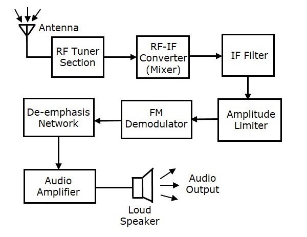
This block diagram of FM receiver is similar to the block diagram of AM receiver. The two blocks Amplitude limiter and De-emphasis network are included before and after FM demodulator. The operation of the remaining blocks is the same as that of AM receiver.
We know that in FM modulation, the amplitude of FM wave remains constant. However, if some noise is added with FM wave in the channel, due to that the amplitude of FM wave may vary. Thus, with the help of amplitude limiter we can maintain the amplitude of FM wave as constant by removing the unwanted peaks of the noise signal.
In FM transmitter, we have seen the pre-emphasis network (High pass filter), which is present before FM modulator. This is used to improve the SNR of high frequency audio signal. The reverse process of pre-emphasis is known as de-emphasis. Thus, in this FM receiver, the de-emphasis network (Low pass filter) is included after FM demodulator. This signal is passed to the audio amplifier to increase the power level. Finally, we get the original sound signal from the loudspeaker.
