- Analog Communication - Home
- Introduction
- Modulation
- Amplitude Modulation
- Numerical Problems 1
- AM Modulators
- AM Demodulators
- DSBSC Modulation
- DSBSC Modulators
- DSBSC Demodulators
- SSBSC Modulation
- SSBSC Modulators
- SSBSC Demodulator
- VSBSC Modulation
- Angle Modulation
- Numerical Problems 2
- FM Modulators
- FM Demodulators
- Multiplexing
- Noise
- SNR Calculations
- Transmitters
- Receivers
- Sampling
- Pulse Modulation
- Transducers
Analog Communication - AM Demodulators
The process of extracting an original message signal from the modulated wave is known as detection or demodulation. The circuit, which demodulates the modulated wave is known as the demodulator. The following demodulators (detectors) are used for demodulating AM wave.
- Square Law Demodulator
- Envelope Detector
Square Law Demodulator
Square law demodulator is used to demodulate low level AM wave. Following is the block diagram of thesquare law demodulator.
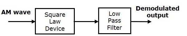
This demodulator contains a square law device and low pass filter. The AM wave $V_1\left ( t \right )$ is applied as an input to this demodulator.
The standard form of AM wave is
$$V_1\left ( t \right )=A_c\left [ 1+k_am\left ( t \right ) \right ] \cos\left ( 2 \pi f_ct \right )$$
We know that the mathematical relationship between the input and the output of square law device is
$V_2\left ( t \right )=k_1V_1\left ( t \right )+k_2V_1^2\left ( t \right )$(Equation 1)
Where,
$V_1\left ( t \right )$ is the input of the square law device, which is nothing but the AM wave
$V_2\left ( t \right )$ is the output of the square law device
$k_1$ and $k_2$ are constants
Substitute $V_1\left ( t \right )$ in Equation 1
$$V_2\left ( t \right )=k_1\left ( A_c\left [ 1+k_am\left ( t \right ) \right ] \cos\left ( 2 \pi f_ct \right )\right )+k_2\left ( A_c\left [ 1+k_am\left ( t \right ) \right ] \cos\left ( 2 \pi f_ct \right )\right )^2$$
$\Rightarrow V_2\left ( t \right )=k_1A_c \cos \left ( 2 \pi f_ct \right )+k_1A_ck_am\left ( t \right ) \cos \left ( 2 \pi f_ct \right )+$
$k_2{A_{c}}^{2}\left [ 1+{K_{a}}^{2}m^2\left ( t \right )+2k_am\left ( t \right ) \right ]\left ( \frac{1+ \cos\left ( 4 \pi f_ct \right )}{2} \right )$
$\Rightarrow V_2\left ( t \right )=k_1A_c \cos \left ( 2 \pi f_ct \right )+k_1A_ck_am\left ( t \right ) \cos \left ( 2 \pi f_ct \right)+\frac{K_2{A_{c}}^{2}}{2}+$
$\frac{K_2{A_{c}}^{2}}{2} \cos \left ( 4 \pi f_ct \right )+\frac{k_2 {A_{c}}^{2}{k_{a}}^{2}m^2\left ( t \right )}{2}+\frac{k_2 {A_{c}}^{2}{k_{a}}^{2}m^2\left ( t \right )}{2} \cos\left ( 4 \pi f_ct \right )+$
$k_2{A_{c}}^{2}k_am\left ( t \right )+k_2{A_{c}}^{2}k_am\left ( t \right )\cos \left ( 4 \pi f_ct \right )$
In the above equation, the term $k_2{A_{c}}^{2}k_am\left ( t \right )$ is the scaled version of the message signal. It can be extracted by passing the above signal through a low pass filter and the DC component $\frac{k_2{A_{c}}^{2}}{2}$ can be eliminated with the help of a coupling capacitor.
Envelope Detector
Envelope detector is used to detect (demodulate) high level AM wave. Following is the block diagram of the envelope detector.
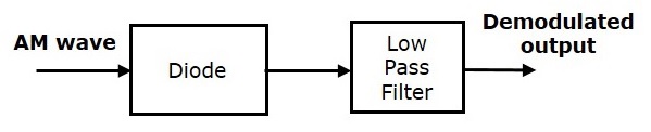
This envelope detector consists of a diode and low pass filter. Here, the diode is the main detecting element. Hence, the envelope detector is also called as the diode detector. The low pass filter contains a parallel combination of the resistor and the capacitor.
The AM wave $s\left ( t \right )$ is applied as an input to this detector.
We know the standard form of AM wave is
$$s\left ( t \right )=A_c\left [ 1+k_am\left ( t \right ) \right ] \cos\left ( 2 \pi f_ct \right )$$
In the positive half cycle of AM wave, the diode conducts and the capacitor charges to the peak value of AM wave. When the value of AM wave is less than this value, the diode will be reverse biased. Thus, the capacitor will discharge through resistor R till the next positive half cycle of AM wave. When the value of AM wave is greater than the capacitor voltage, the diode conducts and the process will be repeated.
We should select the component values in such a way that the capacitor charges very quickly and discharges very slowly. As a result, we will get the capacitor voltage waveform same as that of the envelope of AM wave, which is almost similar to the modulating signal.
