- Analog Communication - Home
- Introduction
- Modulation
- Amplitude Modulation
- Numerical Problems 1
- AM Modulators
- AM Demodulators
- DSBSC Modulation
- DSBSC Modulators
- DSBSC Demodulators
- SSBSC Modulation
- SSBSC Modulators
- SSBSC Demodulator
- VSBSC Modulation
- Angle Modulation
- Numerical Problems 2
- FM Modulators
- FM Demodulators
- Multiplexing
- Noise
- SNR Calculations
- Transmitters
- Receivers
- Sampling
- Pulse Modulation
- Transducers
Analog Communication - FM Demodulators
In this chapter, let us discuss about the demodulators which demodulate the FM wave. The following two methods demodulate FM wave.
- Frequency discrimination method
- Phase discrimination method
Frequency Discrimination Method
We know that the equation of FM wave is
$$s\left ( t \right ) =A_c \cos \left ( 2 \pi f_ct+2 \pi k_f \int m\left ( t \right )dt \right )$$
Differentiate the above equation with respect to 't'.
$$\frac{ds\left ( t \right )}{dt}= -A_c\left ( 2 \pi f_c+2 \pi k_fm\left ( t \right ) \right ) \sin\left ( 2 \pi f_ct+2 \pi k_f\int m\left ( t \right )dt \right )$$
We can write, $-\sin \theta$ as $\sin \left ( \theta -180^0 \right )$.
$$\Rightarrow \frac{ds(t)}{dt}=A_c\left ( 2 \pi f_c+2 \pi k_fm\left ( t \right ) \right )\sin\left ( 2 \pi f_ct+2 \pi k_f \int m\left ( t \right )dt-180^0 \right )$$
$$\Rightarrow \frac{ds(t)}{dt}=A_c\left ( 2 \pi f_c \right )\left [ 1+\left ( \frac{k_f}{k_c} \right )m\left ( t \right ) \right ] \sin\left ( 2 \pi f_ct+2 \pi k_f\int m\left ( t \right )dt-180^0 \right )$$
In the above equation, the amplitude term resembles the envelope of AM wave and the angle term resembles the angle of FM wave. Here, our requirement is the modulating signal $m\left ( t \right )$. Hence, we can recover it from the envelope of AM wave.
The following figure shows the block diagram of FM demodulator using frequency discrimination method.
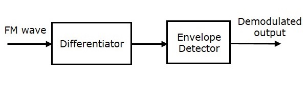
This block diagram consists of the differentiator and the envelope detector. Differentiator is used to convert the FM wave into a combination of AM wave and FM wave. This means, it converts the frequency variations of FM wave into the corresponding voltage (amplitude) variations of AM wave. We know the operation of the envelope detector. It produces the demodulated output of AM wave, which is nothing but the modulating signal.
Phase Discrimination Method
The following figure shows the block diagram of FM demodulator using phase discrimination method.
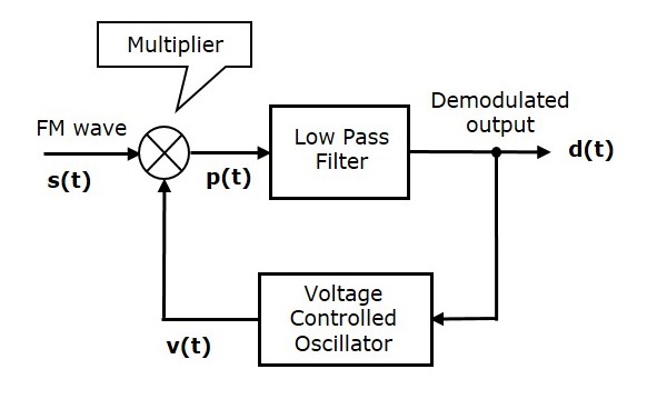
This block diagram consists of the multiplier, the low pass filter, and the Voltage Controlled Oscillator (VCO). VCO produces an output signal $v \left ( t \right )$, whose frequency is proportional to the input signal voltage $d \left ( t \right )$. Initially, when the signal $d \left ( t \right )$ is zero, adjust the VCO to produce an output signal $v \left ( t \right )$, having a carrier frequency and $-90^0$ phase shift with respect to the carrier signal.
FM wave $s \left ( t \right )$ and the VCO output $v \left ( t \right )$ are applied as inputs of the multiplier. The multiplier produces an output, having a high frequency component and a low frequency component. Low pass filter eliminates the high frequency component and produces only the low frequency component as its output.
This low frequency component contains only the term-related phase difference. Hence, we get the modulating signal $m \left ( t \right )$ from this output of the low pass filter.
