- Analog Communication - Home
- Introduction
- Modulation
- Amplitude Modulation
- Numerical Problems 1
- AM Modulators
- AM Demodulators
- DSBSC Modulation
- DSBSC Modulators
- DSBSC Demodulators
- SSBSC Modulation
- SSBSC Modulators
- SSBSC Demodulator
- VSBSC Modulation
- Angle Modulation
- Numerical Problems 2
- FM Modulators
- FM Demodulators
- Multiplexing
- Noise
- SNR Calculations
- Transmitters
- Receivers
- Sampling
- Pulse Modulation
- Transducers
Analog Communication - Pulse Modulation
After continuous wave modulation, the next division is Pulse modulation. In this chapter, let us discuss the following analog pulse modulation techniques.
- Pulse Amplitude Modulation
- Pulse Width Modulation
- Pulse Position Modulation
Pulse Amplitude Modulation
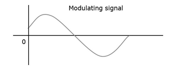
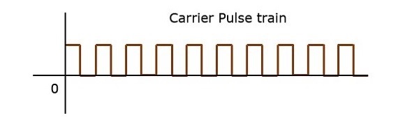
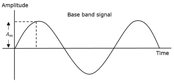
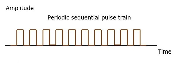
In Pulse Amplitude Modulation (PAM) technique, the amplitude of the pulse carrier varies, which is proportional to the instantaneous amplitude of the message signal.
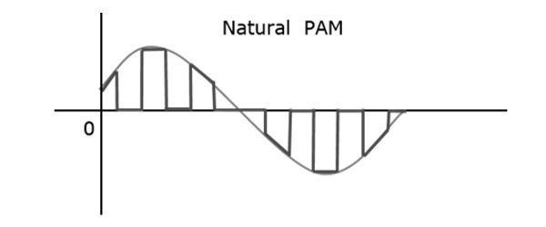
The pulse amplitude modulated signal will follow the amplitude of the original signal, as the signal traces out the path of the whole wave. In natural PAM, a signal sampled at Nyquist rate can be reconstructed, by passing it through an efficient Low Pass Filter (LPF) with exact cutoff frequency.
The following figures explain the Pulse Amplitude Modulation.
Though the PAM signal is passed through a LPF, it cannot recover the signal without distortion. Hence, to avoid this noise, use flat-top sampling. The flat-top PAM signal is shown in the following figure.
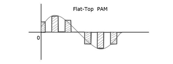
Flat-top sampling is the process in which, the sampled signal can be represented in pulses for which the amplitude of the signal cannot be changed with respect to the analog signal, to be sampled. The tops of amplitude remain flat. This process simplifies the circuit design.
Pulse Width Modulation
In Pulse Width Modulation (PWM) or Pulse Duration Modulation (PDM) or Pulse Time Modulation (PTM) technique, the width or the duration or the time of the pulse carrier varies, which is proportional to the instantaneous amplitude of the message signal.
The width of the pulse varies in this method, but the amplitude of the signal remains constant. Amplitude limiters are used to make the amplitude of the signal constant. These circuits clip off the amplitude to a desired level, and hence the noise is limited.
The following figure explains the types of Pulse Width Modulations.
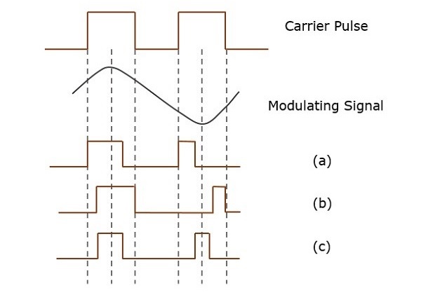
There are three types of PWM.
The leading edge of the pulse being constant, the trailing edge varies according to the message signal. The waveform for this type of PWM is denoted as (a) in the above figure.
The trailing edge of the pulse being constant, the leading edge varies according to the message signal. The waveform for this type of PWM is denoted as (b) in the above figure.
The center of the pulse being constant, the leading edge and the trailing edge varies according to the message signal. The waveform for this type of PWM is denoted as (c) shown in the above figure.
Pulse Position Modulation
Pulse Position Modulation (PPM) is an analog modulation scheme in which, the amplitude and the width of the pulses are kept constant, while the position of each pulse, with reference to the position of a reference pulse varies according to the instantaneous sampled value of the message signal.
The transmitter has to send synchronizing pulses (or simply sync pulses) to keep the transmitter and the receiver in sync. These sync pulses help to maintain the position of the pulses. The following figures explain the Pulse Position Modulation.
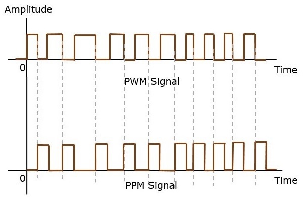
Pulse position modulation is done in accordance with the pulse width modulated signal. Each trailing edge of the pulse width modulated signal becomes the starting point for pulses in PPM signal. Hence, the position of these pulses is proportional to the width of the PWM pulses.
Advantage
As the amplitude and the width are constant, the power handled is also constant.
Disadvantage
The synchronization between the transmitter and the receiver is a must.
Comparison between PAM, PWM, and PPM
The following table presents the comparison between three modulation techniques.
| PAM | PWM | PPM |
|---|---|---|
| Amplitude is varied | Width is varied | Position is varied |
| Bandwidth depends on the width of the pulse | Bandwidth depends on the rise time of the pulse | Bandwidth depends on the rise time of the pulse |
| Instantaneous transmitter power varies with the amplitude of the pulses | Instantaneous transmitter power varies with the amplitude and the width of the pulses | Instantaneous transmitter power remains constant with the width of the pulses |
| System complexity is high | System complexity is low | System complexity is low |
| Noise interference is high | Noise interference is low | Noise interference is low |
| It is similar to amplitude modulation | It is similar to frequency modulation | It is similar to phase modulation |
