- Transistors - Overview
- Transistor Configurations
- Transistor Regions of Operation
- Transistor Load Line Analysis
- Operating Point
- Transistor as an Amplifier
- Transistor Biasing
- Methods of Transistor Biasing
- Bias Compensation
- Amplifiers
- Basic Amplifier
- Classification of Amplifiers
- Based on Configurations
- Multi-Stage Transistor Amplifier
- RC Coupling Amplifier
- Transformer Coupled Amplifier
- Direct Coupled Amplifier
- Power Amplifiers
- Classification of Power Amplifiers
- Class A Power Amplifiers
- Transformer Coupled Class A Power Amplifier
- Push-Pull Class A Power Amplifier
- Class B Power Amplifier
- Class AB and C Power Amplifiers
- Tuned Amplifiers
- Types of Tuned Amplifiers
- Feedback Amplifiers
- Negative Feedback Amplifiers
- Emitter Follower & Darlington Amplifier
- Noise in Amplifiers
- Amplifiers Useful Resources
- Amplifiers - Quick Guide
- Amplifiers - Useful Resources
- Amplifiers - Discussion
Types of Tuned Amplifiers
There are two main types of tuned amplifiers. They are −
- Single tuned amplifier
- Double tuned amplifier
Single Tuned Amplifier
An amplifier circuit with a single tuner section being at the collector of the amplifier circuit is called as Single tuner amplifier circuit.
Construction
A simple transistor amplifier circuit consisting of a parallel tuned circuit in its collector load, makes a single tuned amplifier circuit. The values of capacitance and inductance of the tuned circuit are selected such that its resonant frequency is equal to the frequency to be amplified.
The following circuit diagram shows a single tuned amplifier circuit.
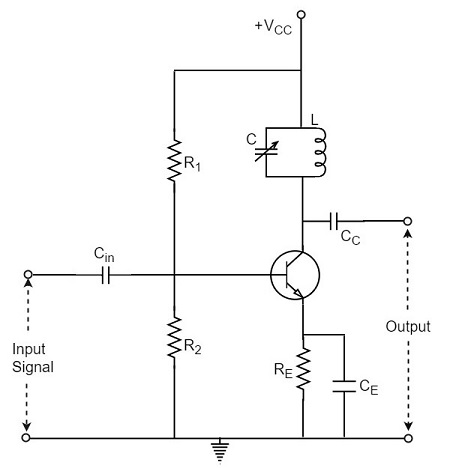
The output can be obtained from the coupling capacitor CC as shown above or from a secondary winding placed at L.
Operation
The high frequency signal that has to be amplified is applied at the input of the amplifier. The resonant frequency of the parallel tuned circuit is made equal to the frequency of the signal applied by altering the capacitance value of the capacitor C, in the tuned circuit.
At this stage, the tuned circuit offers high impedance to the signal frequency, which helps to offer high output across the tuned circuit. As high impedance is offered only for the tuned frequency, all the other frequencies which get lower impedance are rejected by the tuned circuit. Hence the tuned amplifier selects and amplifies the desired frequency signal.
Frequency Response
The parallel resonance occurs at resonant frequency fr when the circuit has a high Q. the resonant frequency fr is given by
$$f_r = \frac{1}{2 \pi \sqrt{LC}}$$
The following graph shows the frequency response of a single tuned amplifier circuit.
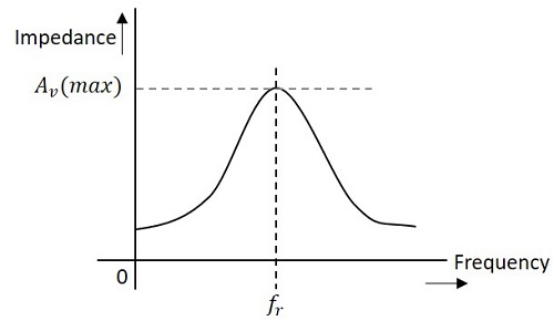
At resonant frequency fr the impedance of parallel tuned circuit is very high and is purely resistive. The voltage across RL is therefore maximum, when the circuit is tuned to resonant frequency. Hence the voltage gain is maximum at resonant frequency and drops off above and below it. The higher the Q, the narrower will the curve be.
Double Tuned Amplifier
An amplifier circuit with a double tuner section being at the collector of the amplifier circuit is called as Double tuner amplifier circuit.
Construction
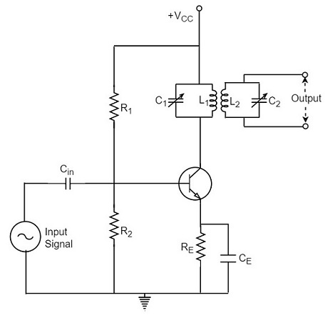
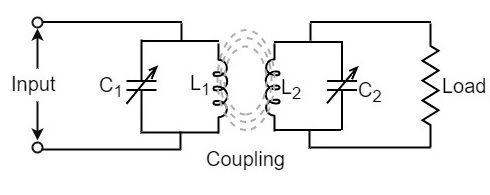
The construction of double tuned amplifier is understood by having a look at the following figure. This circuit consists of two tuned circuits L1C1 and L2C2 in the collector section of the amplifier. The signal at the output of the tuned circuit L1C1 is coupled to the other tuned circuit L2C2 through mutual coupling method. The remaining circuit details are same as in the single tuned amplifier circuit, as shown in the following circuit diagram.
Operation
The high frequency signal which has to be amplified is given to the input of the amplifier. The tuning circuit L1C1 is tuned to the input signal frequency. At this condition, the tuned circuit offers high reactance to the signal frequency. Consequently, large output appears at the output of the tuned circuit L1C1 which is then coupled to the other tuned circuit L2C2 through mutual induction. These double tuned circuits are extensively used for coupling various circuits of radio and television receivers.
Frequency Response of Double Tuned Amplifier
The double tuned amplifier has the special feature of coupling which is important in determining the frequency response of the amplifier. The amount of mutual inductance between the two tuned circuits states the degree of coupling, which determines the frequency response of the circuit.
In order to have an idea on the mutual inductance property, let us go through the basic principle.
Mutual Inductance
As the current carrying coil produces some magnetic field around it, if another coil is brought near this coil, such that it is in the magnetic flux region of the primary, then the varying magnetic flux induces an EMF in the second coil. If this first coil is called as Primary coil, the second one can be called as a Secondary coil.
When the EMF is induced in the secondary coil due to the varying magnetic field of the primary coil, then such phenomenon is called as the Mutual Inductance.
The figure below gives an idea about this.
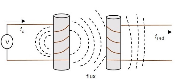
The current is in the figure indicate the source current while iind indicates the induced current. The flux represents the magnetic flux created around the coil. This spreads to the secondary coil also.
With the application of voltage, the current is flows and flux gets created. When the current is varies the flux gets varied, producing iind in the secondary coil, due to the Mutual inductance property.
Coupling
Under the concept of mutual inductance coupling will be as shown in the figure below.
When the coils are spaced apart, the flux linkages of primary coil L1 will not link the secondary coil L2. At this condition, the coils are said to have Loose coupling. The resistance reflected from the secondary coil at this condition is small and the resonance curve will be sharp and the circuit Q is high as shown in the figure below.

On the contrary, when the primary and secondary coils are brought close together, they have Tight coupling. Under such conditions, the reflected resistance will be large and the circuit Q is lower. Two positions of gain maxima, one above and the other below the resonant frequency are obtained.
Bandwidth of Double Tuned Circuit
The above figure clearly states that the bandwidth increases with the degree of coupling. The determining factor in a double tuned circuit is not Q but the coupling.
We understood that, for a given frequency, the tighter the coupling the greater the bandwidth will be.
The equation for bandwidth is given as
$$BW_{dt} = k f_r$$
Where BWdt = bandwidth for double tuned circuit, K = coefficient of coupling, and fr = resonant frequency.
We hope that now you have gained sufficient knowledge regarding the functioning of tuned amplifiers. In the next chapter, we will learn about feedback amplifiers.
