- Transistors - Overview
- Transistor Configurations
- Transistor Regions of Operation
- Transistor Load Line Analysis
- Operating Point
- Transistor as an Amplifier
- Transistor Biasing
- Methods of Transistor Biasing
- Bias Compensation
- Amplifiers
- Basic Amplifier
- Classification of Amplifiers
- Based on Configurations
- Multi-Stage Transistor Amplifier
- RC Coupling Amplifier
- Transformer Coupled Amplifier
- Direct Coupled Amplifier
- Power Amplifiers
- Classification of Power Amplifiers
- Class A Power Amplifiers
- Transformer Coupled Class A Power Amplifier
- Push-Pull Class A Power Amplifier
- Class B Power Amplifier
- Class AB and C Power Amplifiers
- Tuned Amplifiers
- Types of Tuned Amplifiers
- Feedback Amplifiers
- Negative Feedback Amplifiers
- Emitter Follower & Darlington Amplifier
- Noise in Amplifiers
- Amplifiers Useful Resources
- Amplifiers - Quick Guide
- Amplifiers - Useful Resources
- Amplifiers - Discussion
Class AB and Class C Power Amplifiers
The class A and class B amplifier so far discussed has got few limitations. Let us now try to combine these two to get a new circuit which would have all the advantages of both class A and class B amplifier without their inefficiencies. Before that, let us also go through another important problem, called as Cross over distortion, the output of class B encounters with.
Cross-over Distortion
In the push-pull configuration, the two identical transistors get into conduction, one after the other and the output produced will be the combination of both.
When the signal changes or crosses over from one transistor to the other at the zero voltage point, it produces an amount of distortion to the output wave shape. For a transistor in order to conduct, the base emitter junction should cross 0.7v, the cut off voltage. The time taken for a transistor to get ON from OFF or to get OFF from ON state is called the transition period.
At the zero voltage point, the transition period of switching over the transistors from one to the other, has its effect which leads to the instances where both the transistors are OFF at a time. Such instances can be called as Flat spot or Dead band on the output wave shape.
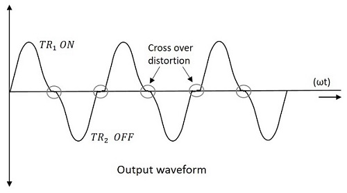
The above figure clearly shows the cross over distortion which is prominent in the output waveform. This is the main disadvantage. This cross over distortion effect also reduces the overall peak to peak value of the output waveform which in turn reduces the maximum power output. This can be more clearly understood through the non-linear characteristic of the waveform as shown below.
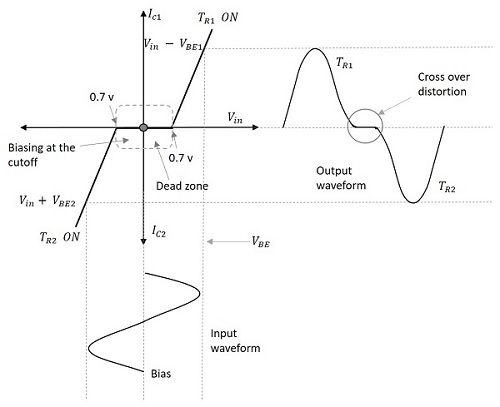
It is understood that this cross-over distortion is less pronounced for large input signals, where as it causes severe disturbance for small input signals. This cross over distortion can be eliminated if the conduction of the amplifier is more than one half cycle, so that both the transistors wont be OFF at the same time.
This idea leads to the invention of class AB amplifier, which is the combination of both class A and class B amplifiers, as discussed below.
Class AB Power Amplifier
As the name implies, class AB is a combination of class A and class B type of amplifiers. As class A has the problem of low efficiency and class B has distortion problem, this class AB is emerged to eliminate these two problems, by utilizing the advantages of both the classes.
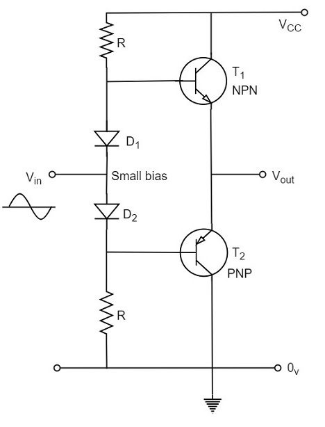
The cross over distortion is the problem that occurs when both the transistors are OFF at the same instant, during the transition period. In order to eliminate this, the condition has to be chosen for more than one half cycle. Hence, the other transistor gets into conduction, before the operating transistor switches to cut off state. This is achieved only by using class AB configuration, as shown in the following circuit diagram.
Therefore, in class AB amplifier design, each of the push-pull transistors is conducting for slightly more than the half cycle of conduction in class B, but much less than the full cycle of conduction of class A.
The conduction angle of class AB amplifier is somewhere between 180o to 360o depending upon the operating point selected. This is understood with the help of below figure.
The small bias voltage given using diodes D1 and D2, as shown in the above figure, helps the operating point to be above the cutoff point. Hence the output waveform of class AB results as seen in the above figure. The crossover distortion created by class B is overcome by this class AB, as well the inefficiencies of class A and B dont affect the circuit.
So, the class AB is a good compromise between class A and class B in terms of efficiency and linearity having the efficiency reaching about 50% to 60%. The class A, B and AB amplifiers are called as linear amplifiers because the output signal amplitude and phase are linearly related to the input signal amplitude and phase.
Class C Power Amplifier
When the collector current flows for less than half cycle of the input signal, the power amplifier is known as class C power amplifier.
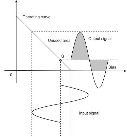
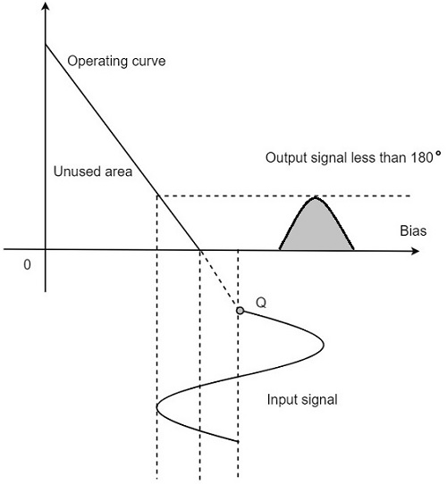
The efficiency of class C amplifier is high while linearity is poor. The conduction angle for class C is less than 180o. It is generally around 90o, which means the transistor remains idle for more than half of the input signal. So, the output current will be delivered for less time compared to the application of input signal.
The following figure shows the operating point and output of a class C amplifier.
This kind of biasing gives a much improved efficiency of around 80% to the amplifier, but introduces heavy distortion in the output signal. Using the class C amplifier, the pulses produced at its output can be converted to complete sine wave of a particular frequency by using LC circuits in its collector circuit.
