- Transistors - Overview
- Transistor Configurations
- Transistor Regions of Operation
- Transistor Load Line Analysis
- Operating Point
- Transistor as an Amplifier
- Transistor Biasing
- Methods of Transistor Biasing
- Bias Compensation
- Amplifiers
- Basic Amplifier
- Classification of Amplifiers
- Based on Configurations
- Multi-Stage Transistor Amplifier
- RC Coupling Amplifier
- Transformer Coupled Amplifier
- Direct Coupled Amplifier
- Power Amplifiers
- Classification of Power Amplifiers
- Class A Power Amplifiers
- Transformer Coupled Class A Power Amplifier
- Push-Pull Class A Power Amplifier
- Class B Power Amplifier
- Class AB and C Power Amplifiers
- Tuned Amplifiers
- Types of Tuned Amplifiers
- Feedback Amplifiers
- Negative Feedback Amplifiers
- Emitter Follower & Darlington Amplifier
- Noise in Amplifiers
- Amplifiers Useful Resources
- Amplifiers - Quick Guide
- Amplifiers - Useful Resources
- Amplifiers - Discussion
Transistor Biasing
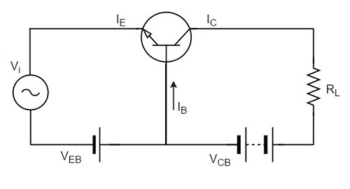
Biasing is the process of providing DC voltage which helps in the functioning of the circuit. A transistor is based in order to make the emitter base junction forward biased and collector base junction reverse biased, so that it maintains in active region, to work as an amplifier.
In the previous chapter, we explained how a transistor acts as a good amplifier, if both the input and output sections are biased.
Transistor Biasing
The proper flow of zero signal collector current and the maintenance of proper collectoremitter voltage during the passage of signal is known as Transistor Biasing. The circuit which provides transistor biasing is called as Biasing Circuit.
Need for DC biasing
If a signal of very small voltage is given to the input of BJT, it cannot be amplified. Because, for a BJT, to amplify a signal, two conditions have to be met.
The input voltage should exceed cut-in voltage for the transistor to be ON.
The BJT should be in the active region, to be operated as an amplifier.
If appropriate DC voltages and currents are given through BJT by external sources, so that BJT operates in active region and superimpose the AC signals to be amplified, then this problem can be avoided. The given DC voltage and currents are so chosen that the transistor remains in active region for entire input AC cycle. Hence DC biasing is needed.
The below figure shows a transistor amplifier that is provided with DC biasing on both input and output circuits.
For a transistor to be operated as a faithful amplifier, the operating point should be stabilized. Let us have a look at the factors that affect the stabilization of operating point.
Factors affecting the operating point
The main factor that affect the operating point is the temperature. The operating point shifts due to change in temperature.
As temperature increases, the values of ICE, β, VBE gets affected.
- ICBO gets doubled (for every 10o rise)
- VBE decreases by 2.5mv (for every 1o rise)
So the main problem which affects the operating point is temperature. Hence operating point should be made independent of the temperature so as to achieve stability. To achieve this, biasing circuits are introduced.
Stabilization
The process of making the operating point independent of temperature changes or variations in transistor parameters is known as Stabilization.
Once the stabilization is achieved, the values of IC and VCE become independent of temperature variations or replacement of transistor. A good biasing circuit helps in the stabilization of operating point.
Need for Stabilization
Stabilization of the operating point has to be achieved due to the following reasons.
- Temperature dependence of IC
- Individual variations
- Thermal runaway
Let us understand these concepts in detail.
Temperature Dependence of IC
As the expression for collector current IC is
$$I_C = \beta I_B + I_{CEO}$$
$$= \beta I_B + (\beta + 1) I_{CBO}$$
The collector leakage current ICBO is greatly influenced by temperature variations. To come out of this, the biasing conditions are set so that zero signal collector current IC = 1 mA. Therefore, the operating point needs to be stabilized i.e. it is necessary to keep IC constant.
Individual Variations
As the value of β and the value of VBE are not same for every transistor, whenever a transistor is replaced, the operating point tends to change. Hence it is necessary to stabilize the operating point.
Thermal Runaway
As the expression for collector current IC is
$$I_C = \beta I_B + I_{CEO}$$
$$= \beta I_B + (\beta + 1)I_{CBO}$$
The flow of collector current and also the collector leakage current causes heat dissipation. If the operating point is not stabilized, there occurs a cumulative effect which increases this heat dissipation.
The self-destruction of such an unstabilized transistor is known as Thermal run away.
In order to avoid thermal runaway and the destruction of transistor, it is necessary to stabilize the operating point, i.e., to keep IC constant.
Stability Factor
It is understood that IC should be kept constant in spite of variations of ICBO or ICO. The extent to which a biasing circuit is successful in maintaining this is measured by Stability factor. It denoted by S.
By definition, the rate of change of collector current IC with respect to the collector leakage current ICO at constant β and IB is called Stability factor.
$S = \frac{d I_C}{d I_{CO}}$ at constant IB and β
Hence we can understand that any change in collector leakage current changes the collector current to a great extent. The stability factor should be as low as possible so that the collector current doesnt get affected. S=1 is the ideal value.
The general expression of stability factor for a CE configuration can be obtained as under.
$$I_C = \beta I_B + (\beta + 1)I_{CO}$$
Differentiating above expression with respect to IC, we get
$$1 = \beta \frac{d I_B}{d I_C} + (\beta + 1)\frac{d I_{CO}}{dI_C}$$
Or
$$1 = \beta \frac{d I_B}{d I_C} + \frac{(\beta + 1)}{S}$$
Since $\frac{d I_{CO}}{d I_C} = \frac{1}{S}$
Or
$$S = \frac{\beta + 1}{1 - \beta \left (\frac{d I_B}{d I_C} \right )}$$
Hence the stability factor S depends on β, IB and IC.
