- Transistors - Overview
- Transistor Configurations
- Transistor Regions of Operation
- Transistor Load Line Analysis
- Operating Point
- Transistor as an Amplifier
- Transistor Biasing
- Methods of Transistor Biasing
- Bias Compensation
- Amplifiers
- Basic Amplifier
- Classification of Amplifiers
- Based on Configurations
- Multi-Stage Transistor Amplifier
- RC Coupling Amplifier
- Transformer Coupled Amplifier
- Direct Coupled Amplifier
- Power Amplifiers
- Classification of Power Amplifiers
- Class A Power Amplifiers
- Transformer Coupled Class A Power Amplifier
- Push-Pull Class A Power Amplifier
- Class B Power Amplifier
- Class AB and C Power Amplifiers
- Tuned Amplifiers
- Types of Tuned Amplifiers
- Feedback Amplifiers
- Negative Feedback Amplifiers
- Emitter Follower & Darlington Amplifier
- Noise in Amplifiers
- Amplifiers Useful Resources
- Amplifiers - Quick Guide
- Amplifiers - Useful Resources
- Amplifiers - Discussion
Bias Compensation
So far we have seen different stabilization techniques. The stabilization occurs due to negative feedback action. The negative feedback, although improves the stability of operating point, it reduces the gain of the amplifier.
As the gain of the amplifier is a very important consideration, some compensation techniques are used to maintain excellent bias and thermal stabilization. Let us now go through such bias compensation techniques.
Diode Compensation for Instability
These are the circuits that implement compensation techniques using diodes to deal with biasing instability. The stabilization techniques refer to the use of resistive biasing circuits which permit IB to vary so as to keep IC relatively constant.
There are two types of diode compensation methods. They are −
- Diode compensation for instability due to VBE variation
- Diode compensation for instability due to ICO variation
Let us understand these two compensation methods in detail.
Diode Compensation for Instability due to VBE Variation
In a Silicon transistor, the changes in the value of VBE results in the changes in IC. A diode can be employed in the emitter circuit in order to compensate the variations in VBE or ICO. As the diode and transistor used are of same material, the voltage VD across the diode has same temperature coefficient as VBE of the transistor.
The following figure shows self-bias with stabilization and compensation.
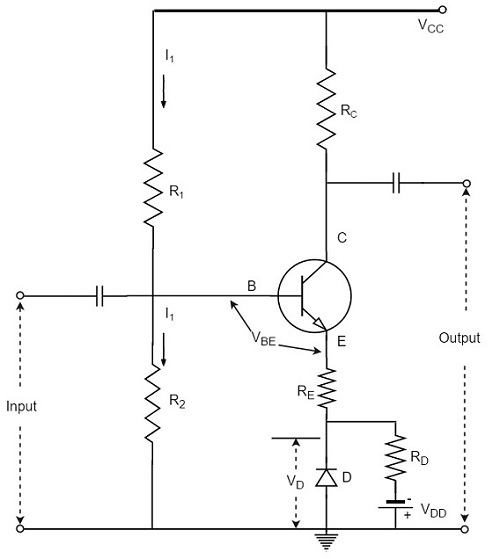
The diode D is forward biased by the source VDD and the resistor RD. The variation in VBE with temperature is same as the variation in VD with temperature, hence the quantity (VBE VD) remains constant. So the current IC remains constant in spite of the variation in VBE.
Diode Compensation for Instability due to ICO Variation
The following figure shows the circuit diagram of a transistor amplifier with diode D used for compensation of variation in ICO.
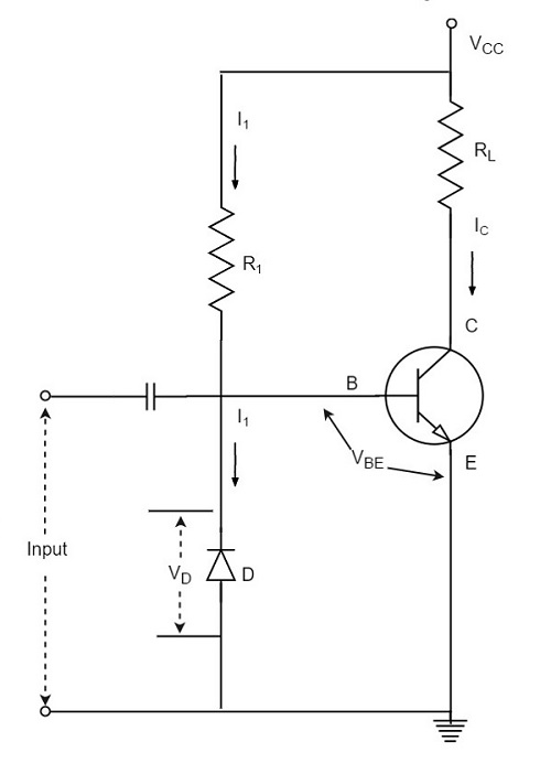
So, the reverse saturation current IO of the diode will increase with temperature at the same rate as the transistor collector saturation current ICO.
$$I = \frac{V_{CC} - V_{BE}}{R} \cong \frac{V_{CC}}{R} = Constant$$
The diode D is reverse biased by VBE and the current through it is the reverse saturation current IO.
Now the base current is,
$$I_B = I - I_O$$
Substituting the above value in the expression for collector current.
$$I_C = \beta (I - I_O) + (1 + \beta)I_{CO}$$
If β ≫ 1,
$$I_C = \beta I - \beta I_O + \beta I_{CO}$$
I is almost constant and if IO of diode and ICO of transistor track each other over the operating temperature range, then IC remains constant.
Other Compensations
There are other compensation techniques which refer to the use of temperature sensitive devices such as diodes, transistors, thermistors, Sensistors, etc. to compensate for the variation in currents.
There are two popular types of circuits in this method, one using a thermistor and the other using a Sensistor. Let us have a look at them.
Thermistor Compensation
Thermistor is a temperature sensitive device. It has negative temperature coefficient. The resistance of a thermistor increases when the temperature decreases and it decreases when the temperature increases. The below figure shows a self-bias amplifier with thermistor compensation.
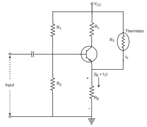
In an amplifier circuit, the changes that occur in ICO, VBE and β with temperature, increases the collector current. Thermistor is employed to minimize the increase in collector current. As the temperature increases, the resistance RT of thermistor decreases, which increases the current through it and the resistor RE. Now, the voltage developed across RE increases, which reverse biases the emitter junction. This reverse bias is so high that the effect of resistors R1 and R2 providing forward bias also gets reduced. This action reduces the rise in collector current.
Thus the temperature sensitivity of thermistor compensates the increase in collector current, occurred due to temperature.
Sensistor Compensation
A Sensistor is a heavily doped semiconductor that has positive temperature coefficient. The resistance of a Sensistor increases with the increase in temperature and decreases with the decrease in temperature. The figure below shows a self-bias amplifier with Sensistor compensation.
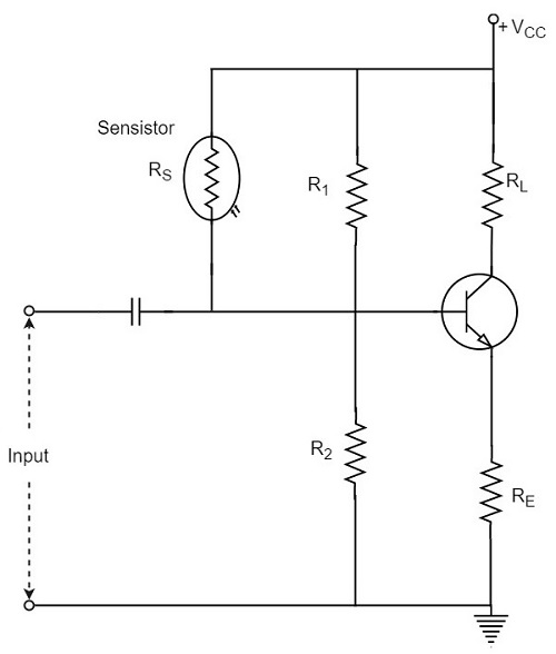
In the above figure, the Sensistor may be placed in parallel with R1 or in parallel with RE. As the temperature increases, the resistance of the parallel combination, thermistor and R1 increases and their voltage drop also increases. This decreases the voltage drop across R2. Due to the decrease of this voltage, the net forward emitter bias decreases. As a result of this, IC decreases.
Hence by employing the Sensistor, the rise in the collector current which is caused by the increase of ICO, VBE and β due to temperature, gets controlled.
Thermal Resistance
The transistor is a temperature dependent device. When the transistor is operated, the collector junction gets heavy flow of electrons and hence has much heat generated. This heat if increased further beyond the permissible limit, damages the junction and thus the transistor.
In order to protect itself from damage, the transistor dissipates heat from the junction to the transistor case and from there to the open air surrounding it.
Let, the ambient temperature or the temperature of surrounding air = TAoC
And, the temperature of collector-base junction of the transistor = TJoC
As TJ > TA, the difference TJ - TA is greater than the power dissipated in the transistor PD will be greater. Thus,
$$T_J - T_A \propto P_D$$
$$T_J - T_A = HP_D$$
Where H is the constant of proportionality, and is called as Thermal resistance.
Thermal resistance is the resistance to heat flow from junction to surrounding air. It is denoted by H.
$$H = \frac{T_J - T_A}{P_D}$$
The unit of H is oC/watt.
If the thermal resistance is low, the transfer of heat from the transistor into the air, will be easy. If the transistor case is larger, the heat dissipation will be better. This is achieved by the use of Heat sink.
Heat Sink
The transistor that handle larger powers, dissipates more heat during operation. This heat if not dissipated properly, could damage the transistor. Hence the power transistors are generally mounted on large metal cases to provide a larger area to get the heat radiated that is generated during its operation.
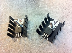
The metal sheet that helps to dissipate the additional heat from the transistor is known as the heat sink. The ability of a heat sink depends upon its material, volume, area, shape, contact between case and sink, and the movement of air around the sink.
The heat sink is selected after considering all these factors. The image shows a power transistor with a heat sink.
A tiny transistor in the above image is fixed to a larger metal sheet in order to dissipate its heat, so that the transistor doesnt get damaged.
Thermal Runaway
The use of heat sink avoids the problem of Thermal Runaway. It is a situation where an increase in temperature leads to the condition that further increase in temperature, leads to the destruction of the device itself. This is a kind of uncontrollable positive feedback.
Heat sink is not the only consideration; other factors such as operating point, ambient temperature, and the type of transistor used can also cause thermal runaway.
