- Transistors - Overview
- Transistor Configurations
- Transistor Regions of Operation
- Transistor Load Line Analysis
- Operating Point
- Transistor as an Amplifier
- Transistor Biasing
- Methods of Transistor Biasing
- Bias Compensation
- Amplifiers
- Basic Amplifier
- Classification of Amplifiers
- Based on Configurations
- Multi-Stage Transistor Amplifier
- RC Coupling Amplifier
- Transformer Coupled Amplifier
- Direct Coupled Amplifier
- Power Amplifiers
- Classification of Power Amplifiers
- Class A Power Amplifiers
- Transformer Coupled Class A Power Amplifier
- Push-Pull Class A Power Amplifier
- Class B Power Amplifier
- Class AB and C Power Amplifiers
- Tuned Amplifiers
- Types of Tuned Amplifiers
- Feedback Amplifiers
- Negative Feedback Amplifiers
- Emitter Follower & Darlington Amplifier
- Noise in Amplifiers
- Amplifiers Useful Resources
- Amplifiers - Quick Guide
- Amplifiers - Useful Resources
- Amplifiers - Discussion
Transistor Regions of Operation
The DC supply is provided for the operation of a transistor. This DC supply is given to the two PN junctions of a transistor which influences the actions of majority carriers in these emitter and collector junctions.
The junctions are forward biased and reverse biased based on our requirement. Forward biased is the condition where a positive voltage is applied to the p-type and negative voltage is applied to the n-type material. Reverse biased is the condition where a positive voltage is applied to the n-type and negative voltage is applied to the p-type material.
Transistor Biasing
The supply of suitable external dc voltage is called as biasing. Either forward or reverse biasing is done to the emitter and collector junctions of the transistor.
These biasing methods make the transistor circuit to work in four kinds of regions such as Active region, Saturation region, Cutoff region and Inverse active region (seldom used). This is understood by having a look at the following table.
| Emitter Junction | Collector Junction | Region of Operation |
|---|---|---|
| Forward biased | Forward biased | Saturation region |
| Forward biased | Reverse biased | Active region |
| Reverse biased | Forward biased | Inverse active region |
| Reverse biased | Reverse biased | Cut off region |
Among these regions, Inverse active region, which is just the inverse of active region, is not suitable for any applications and hence not used.
Active Region
This is the region in which transistors have many applications. This is also called as linear region. A transistor while in this region, acts better as an Amplifier.
The following circuit diagram shows a transistor working in active region.
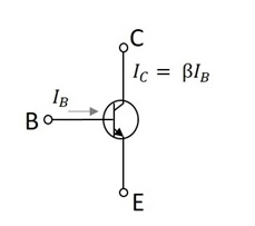
This region lies between saturation and cutoff. The transistor operates in active region when the emitter junction is forward biased and collector junction is reverse biased.
In the active state, collector current is β times the base current, i.e.
$$I_C = \beta I_B$$
Where IC = collector current, β = current amplification factor, and IB = base current.
Saturation Region
This is the region in which transistor tends to behave as a closed switch. The transistor has the effect of its collector and emitter being shorted. The collector and emitter currents are maximum in this mode of operation.
The following figure shows a transistor working in saturation region.
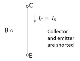
The transistor operates in saturation region when both the emitter and collector junctions are forward biased.
In saturation mode,
$$\beta < \frac{I_C}{I_B}$$
As in the saturation region the transistor tends to behave as a closed switch,
$$I_C = I_E$$
Where IC = collector current and IE = emitter current.
Cutoff Region
This is the region in which transistor tends to behave as an open switch. The transistor has the effect of its collector and base being opened. The collector, emitter and base currents are all zero in this mode of operation.
The figure below shows a transistor working in cutoff region.
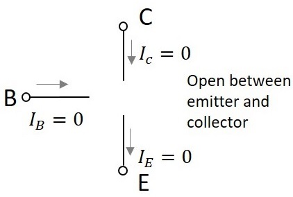
The transistor operates in cutoff region when both the emitter and collector junctions are reverse biased.
As in cutoff region, the collector current, emitter current and base currents are nil, we can write as
$$I_C = I_E = I_B = 0$$
Where IC = collector current, IE = emitter current, and IB = base current.
