- Transistors - Overview
- Transistor Configurations
- Transistor Regions of Operation
- Transistor Load Line Analysis
- Operating Point
- Transistor as an Amplifier
- Transistor Biasing
- Methods of Transistor Biasing
- Bias Compensation
- Amplifiers
- Basic Amplifier
- Classification of Amplifiers
- Based on Configurations
- Multi-Stage Transistor Amplifier
- RC Coupling Amplifier
- Transformer Coupled Amplifier
- Direct Coupled Amplifier
- Power Amplifiers
- Classification of Power Amplifiers
- Class A Power Amplifiers
- Transformer Coupled Class A Power Amplifier
- Push-Pull Class A Power Amplifier
- Class B Power Amplifier
- Class AB and C Power Amplifiers
- Tuned Amplifiers
- Types of Tuned Amplifiers
- Feedback Amplifiers
- Negative Feedback Amplifiers
- Emitter Follower & Darlington Amplifier
- Noise in Amplifiers
- Amplifiers Useful Resources
- Amplifiers - Quick Guide
- Amplifiers - Useful Resources
- Amplifiers - Discussion
Methods of Transistor Biasing
The biasing in transistor circuits is done by using two DC sources VBB and VCC. It is economical to minimize the DC source to one supply instead of two which also makes the circuit simple.
The commonly used methods of transistor biasing are
- Base Resistor method
- Collector to Base bias
- Biasing with Collector feedback resistor
- Voltage-divider bias
All of these methods have the same basic principle of obtaining the required value of IB and IC from VCC in the zero signal conditions.
Base Resistor Method
In this method, a resistor RB of high resistance is connected in base, as the name implies. The required zero signal base current is provided by VCC which flows through RB. The base emitter junction is forward biased, as base is positive with respect to emitter.
The required value of zero signal base current and hence the collector current (as IC = βIB) can be made to flow by selecting the proper value of base resistor RB. Hence the value of RB is to be known. The figure below shows how a base resistor method of biasing circuit looks like.
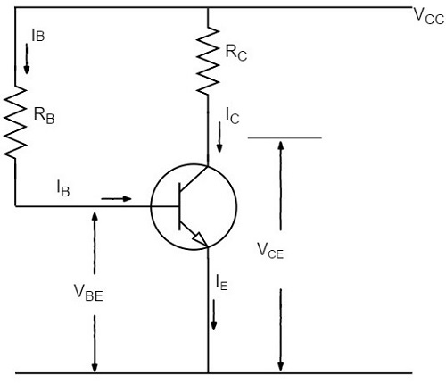
Let IC be the required zero signal collector current. Therefore,
$$I_B = \frac{I_C}{\beta}$$
Considering the closed circuit from VCC, base, emitter and ground, while applying the Kirchhoffs voltage law, we get,
$$V_{CC} = I_B R_B + V_{BE}$$
Or
$$I_B R_B = V_{CC} - V_{BE}$$
Therefore
$$R_B = \frac{V_{CC} - V_{BE}}{I_B}$$
Since VBE is generally quite small as compared to VCC, the former can be neglected with little error. Then,
$$R_B = \frac{V_{CC}}{I_B}$$
We know that VCC is a fixed known quantity and IB is chosen at some suitable value. As RB can be found directly, this method is called as fixed bias method.
Stability factor
$$S = \frac{\beta + 1}{1 - \beta \left ( \frac{d I_B}{d I_C} \right )}$$
In fixed-bias method of biasing, IB is independent of IC so that,
$$\frac{d I_B}{d I_C} = 0$$
Substituting the above value in the previous equation,
Stability factor, $S = \beta + 1$
Thus the stability factor in a fixed bias is (β+1) which means that IC changes (β+1) times as much as any change in ICO.
Advantages
- The circuit is simple.
- Only one resistor RE is required.
- Biasing conditions are set easily.
- No loading effect as no resistor is present at base-emitter junction.
Disadvantages
The stabilization is poor as heat development cant be stopped.
The stability factor is very high. So, there are strong chances of thermal run away.
Hence, this method is rarely employed.
Collector to Base Bias
The collector to base bias circuit is same as base bias circuit except that the base resistor RB is returned to collector, rather than to VCC supply as shown in the figure below.
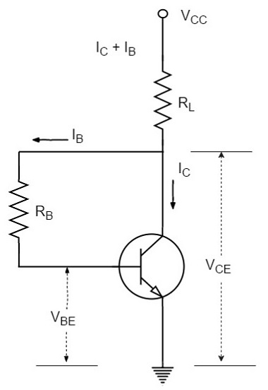
This circuit helps in improving the stability considerably. If the value of IC increases, the voltage across RL increases and hence the VCE also increases. This in turn reduces the base current IB. This action somewhat compensates the original increase.
The required value of RB needed to give the zero signal collector current IC can be calculated as follows.
Voltage drop across RL will be
$$R_L = (I_C + I_B)R_L \cong I_C R_L$$
From the figure,
$$I_C R_L + I_B R_B + V_{BE} = V_{CC}$$
Or
$$I_B R_B = V_{CC} - V_{BE} - I_C R_L$$
Therefore
$$R_B = \frac{V_{CC} - V_{BE} - I_C R_L}{I_B}$$
Or
$$R_B = \frac{(V_{CC} - V_{BE} - I_C R_L)\beta}{I_C}$$
Applying KVL we have
$$(I_B + I_C)R_L + I_B R_B + V_{BE} = V_{CC}$$
Or
$$I_B(R_L + R_B) + I_C R_L + V_{BE} = V_{CC}$$
Therefore
$$I_B = \frac{V_{CC} - V_{BE} - I_C R_L}{R_L + R_B}$$
Since VBE is almost independent of collector current, we get
$$\frac{d I_B}{d I_C} = - \frac{R_L}{R_L + R_B}$$
We know that
$$S = \frac{1 + \beta}{1 - \beta (d I_B / d I_C)}$$
Therefore
$$S = \frac{1 + \beta}{1 + \beta \left ( \frac{R_L}{R_L + R_B} \right )}$$
This value is smaller than (1+β) which is obtained for fixed bias circuit. Thus there is an improvement in the stability.
This circuit provides a negative feedback which reduces the gain of the amplifier. So the increased stability of the collector to base bias circuit is obtained at the cost of AC voltage gain.
Biasing with Collector Feedback resistor
In this method, the base resistor RB has its one end connected to base and the other to the collector as its name implies. In this circuit, the zero signal base current is determined by VCB but not by VCC.
It is clear that VCB forward biases the base-emitter junction and hence base current IB flows through RB. This causes the zero signal collector current to flow in the circuit. The below figure shows the biasing with collector feedback resistor circuit.
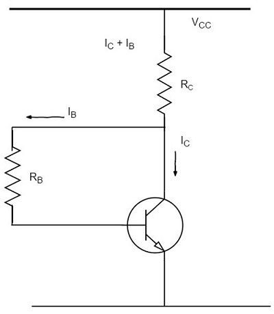
The required value of RB needed to give the zero signal current IC can be determined as follows.
$$V_{CC} = I_C R_C + I_B R_B + V_{BE}$$
Or
$$R_B = \frac{V_{CC} - V_{BE} - I_C R_C}{I_B}$$
$$= \frac{V_{CC} - V_{BE} - \beta I_B R_C}{I_B}$$
Since $I_C = \beta I_B$
Alternatively,
$$V_{CE} = V_{BE} + V_{CB}$$
Or
$$V_{CB} = V_{CE} - V_{BE}$$
Since
$$R_B = \frac{V_{CB}}{I_B} = \frac{V_{CE} - V_{BE}}{I_B}$$
Where
$$I_B = \frac{I_C}{\beta}$$
Mathematically,
Stability factor, $S < (\beta + 1)$
Therefore, this method provides better thermal stability than the fixed bias.
The Q-point values for the circuit are shown as
$$I_C = \frac{V_{CC} - V_{BE}}{R_B/ \beta + R_C}$$
$$V_{CE} = V_{CC} - I_C R_C$$
Advantages
- The circuit is simple as it needs only one resistor.
- This circuit provides some stabilization, for lesser changes.
Disadvantages
- The circuit doesnt provide good stabilization.
- The circuit provides negative feedback.
Voltage Divider Bias Method
Among all the methods of providing biasing and stabilization, the voltage divider bias method is the most prominent one. Here, two resistors R1 and R2 are employed, which are connected to VCC and provide biasing. The resistor RE employed in the emitter provides stabilization.
The name voltage divider comes from the voltage divider formed by R1 and R2. The voltage drop across R2 forward biases the base-emitter junction. This causes the base current and hence collector current flow in the zero signal conditions. The figure below shows the circuit of voltage divider bias method.
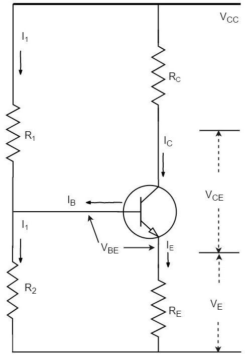
Suppose that the current flowing through resistance R1 is I1. As base current IB is very small, therefore, it can be assumed with reasonable accuracy that current flowing through R2 is also I1.
Now let us try to derive the expressions for collector current and collector voltage.
Collector Current, IC
From the circuit, it is evident that,
$$I_1 = \frac{V_{CC}}{R_1 + R_2}$$
Therefore, the voltage across resistance R2 is
$$V_2 = \left ( \frac{V_{CC}}{R_1 + R_2}\right ) R_2$$
Applying Kirchhoffs voltage law to the base circuit,
$$V_2 = V_{BE} + V_E$$
$$V_2 = V_{BE} + I_E R_E$$
$$I_E = \frac{V_2 - V_{BE}}{R_E}$$
Since IE ≈ IC,
$$I_C = \frac{V_2 - V_{BE}}{R_E}$$
From the above expression, it is evident that IC doesnt depend upon β. VBE is very small that IC doesnt get affected by VBE at all. Thus IC in this circuit is almost independent of transistor parameters and hence good stabilization is achieved.
Collector-Emitter Voltage, VCE
Applying Kirchhoffs voltage law to the collector side,
$$V_{CC} = I_C R_C + V_{CE} + I_E R_E$$
Since IE ≅ IC
$$= I_C R_C + V_{CE} + I_C R_E$$
$$= I_C(R_C + R_E) + V_{CE}$$
Therefore,
$$V_{CE} = V_{CC} - I_C(R_C + R_E)$$
RE provides excellent stabilization in this circuit.
$$V_2 = V_{BE} + I_C R_E$$
Suppose there is a rise in temperature, then the collector current IC decreases, which causes the voltage drop across RE to increase. As the voltage drop across R2 is V2, which is independent of IC, the value of VBE decreases. The reduced value of IB tends to restore IC to the original value.
Stability Factor
The equation for Stability factor of this circuit is obtained as
Stability Factor = $S = \frac{(\beta + 1) (R_0 + R_3)}{R_0 + R_E + \beta R_E}$
$$= (\beta + 1) \times \frac{1 + \frac{R_0}{R_E}}{\beta + 1 + \frac{R_0}{R_E}}$$
Where
$$R_0 = \frac{R_1 R_2}{R_1 + R_2}$$
If the ratio R0/RE is very small, then R0/RE can be neglected as compared to 1 and the stability factor becomes
Stability Factor = $S = (\beta + 1) \times \frac{1}{\beta + 1} = 1$
This is the smallest possible value of S and leads to the maximum possible thermal stability.
