- Transistors - Overview
- Transistor Configurations
- Transistor Regions of Operation
- Transistor Load Line Analysis
- Operating Point
- Transistor as an Amplifier
- Transistor Biasing
- Methods of Transistor Biasing
- Bias Compensation
- Amplifiers
- Basic Amplifier
- Classification of Amplifiers
- Based on Configurations
- Multi-Stage Transistor Amplifier
- RC Coupling Amplifier
- Transformer Coupled Amplifier
- Direct Coupled Amplifier
- Power Amplifiers
- Classification of Power Amplifiers
- Class A Power Amplifiers
- Transformer Coupled Class A Power Amplifier
- Push-Pull Class A Power Amplifier
- Class B Power Amplifier
- Class AB and C Power Amplifiers
- Tuned Amplifiers
- Types of Tuned Amplifiers
- Feedback Amplifiers
- Negative Feedback Amplifiers
- Emitter Follower & Darlington Amplifier
- Noise in Amplifiers
- Amplifiers Useful Resources
- Amplifiers - Quick Guide
- Amplifiers - Useful Resources
- Amplifiers - Discussion
Tuned Amplifiers
The types of amplifiers that we have discussed so far cannot work effectively at radio frequencies, even though they are good at audio frequencies. Also, the gain of these amplifiers is such that it will not vary according to the frequency of the signal, over a wide range. This allows the amplification of the signal equally well over a range of frequencies and does not permit the selection of particular desired frequency while rejecting the other frequencies.
So, there occurs a need for a circuit which can select as well as amplify. So, an amplifier circuit along with a selection, such as a tuned circuit makes a Tuned amplifier.
What is a Tuned Amplifier?
Tuned amplifiers are the amplifiers that are employed for the purpose of tuning. Tuning means selecting. Among a set of frequencies available, if there occurs a need to select a particular frequency, while rejecting all other frequencies, such a process is called Selection. This selection is done by using a circuit called as Tuned circuit.
When an amplifier circuit has its load replaced by a tuned circuit, such an amplifier can be called as a Tuned amplifier circuit. The basic tuned amplifier circuit looks as shown below.
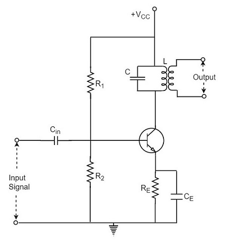
The tuner circuit is nothing but a LC circuit which is also called as resonant or tank circuit. It selects the frequency. A tuned circuit is capable of amplifying a signal over a narrow band of frequencies that are centered at resonant frequency.
When the reactance of the inductor balances the reactance of the capacitor, in the tuned circuit at some frequency, such a frequency can be called as resonant frequency. It is denoted by fr.
The formula for resonance is
$$2 \pi f_L = \frac{1}{2 \pi f_c}$$
$$f_r = \frac{1}{2 \pi \sqrt{LC}}$$
Types of Tuned Circuits
A tuned circuit can be Series tuned circuit (Series resonant circuit) or Parallel tuned circuit (parallel resonant circuit) according to the type of its connection to the main circuit.
Series Tuned Circuit
The inductor and capacitor connected in series make a series tuned circuit, as shown in the following circuit diagram.
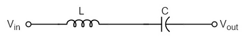
At resonant frequency, a series resonant circuit offers low impedance which allows high current through it. A series resonant circuit offers increasingly high impedance to the frequencies far from the resonant frequency.
Parallel Tuned Circuit
The inductor and capacitor connected in parallel make a parallel tuned circuit, as shown in the below figure.
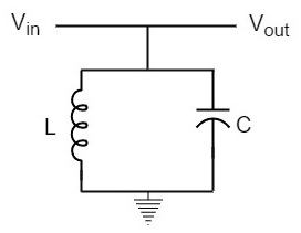
At resonant frequency, a parallel resonant circuit offers high impedance which does not allow high current through it. A parallel resonant circuit offers increasingly low impedance to the frequencies far from the resonant frequency.
Characteristics of a Parallel Tuned Circuit
The frequency at which parallel resonance occurs (i.e. reactive component of circuit current becomes zero) is called the resonant frequency fr. The main characteristics of a tuned circuit are as follows.
Impedance
The ratio of supply voltage to the line current is the impedance of the tuned circuit. Impedance offered by LC circuit is given by
$$\frac{Supply \: voltage}{Line equation} = \frac{V}{I}$$
At resonance, the line current increases while the impedance decreases.
The below figure represents the impedance curve of a parallel resonance circuit.
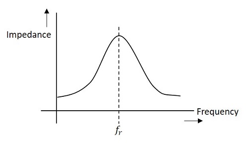
Impedance of the circuit decreases for the values above and below the resonant frequency fr. Hence the selection of a particular frequency and rejection of other frequencies is possible.
To obtain an equation for the circuit impedance, let us consider
Line Current $I = I_L cos \phi$
$$\frac{V}{Z_r} = \frac{V}{Z_L} \times \frac{R}{Z_L}$$
$$\frac{1}{Z_r} = \frac{R}{Z_L^2}$$
$$\frac{1}{Z_r} = \frac{R}{L/C} = \frac{C R}{L}$$
Since, $Z_L^2 = \frac{L}{C}$
Therefore, circuit impedance Zr is obtained as
$$Z_R = \frac{L}{C R}$$
Thus at parallel resonance, the circuit impedance is equal to L/CR.
Circuit Current
At parallel resonance, the circuit or line current I is given by the applied voltage divided by the circuit impedance Zr i.e.,
Line Current $I = \frac{V}{Z_r}$
Where $Z_r = \frac{L}{C R}$
Because Zr is very high, the line current I will be very small.
Quality Factor
For a parallel resonance circuit, the sharpness of the resonance curve determines the selectivity. The smaller the resistance of the coil, the sharper the resonant curve will be. Hence the inductive reactance and resistance of the coil determine the quality of the tuned circuit.
The ratio of inductive reactance of the coil at resonance to its resistance is known as Quality factor. It is denoted by Q.
$$Q = \frac{X_L}{R} = \frac{2 \pi f_r L}{R}$$
The higher the value of Q, the sharper the resonance curve and the better the selectivity will be.
Advantages of Tuned Amplifiers
The following are the advantages of tuned amplifiers.
The usage of reactive components like L and C, minimizes the power loss, which makes the tuned amplifiers efficient.
The selectivity and amplification of desired frequency is high, by providing higher impedance at resonant frequency.
A smaller collector supply VCC would do, because of its little resistance in parallel tuned circuit.
It is important to remember that these advantages are not applicable when there is a high resistive collector load.
Frequency Response of Tuned Amplifier
For an amplifier to be efficient, its gain should be high. This voltage gain depends upon β, input impedance and collector load. The collector load in a tuned amplifier is a tuned circuit.
The voltage gain of such an amplifier is given by
Voltage gain = $\frac{\beta Z_C}{Z_{in}}$
Where ZC = effective collector load and Zin = input impedance of the amplifier.
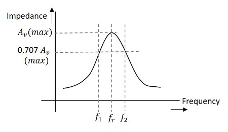
The value of ZC depends upon the frequency of the tuned amplifier. As ZC is maximum at resonant frequency, the gain of the amplifier is maximum at this resonant frequency.
Bandwidth
The range of frequencies at which the voltage gain of the tuned amplifier falls to 70.7% of the maximum gain is called its Bandwidth.
The range of frequencies between f1 and f2 is called as bandwidth of the tuned amplifier. The bandwidth of a tuned amplifier depends upon the Q of the LC circuit i.e., upon the sharpness of the frequency response. The value of Q and the bandwidth are inversely proportional.
The figure below details the bandwidth and frequency response of the tuned amplifier.
Relation between Q and Bandwidth
The quality factor Q of the bandwidth is defined as the ratio of resonant frequency to bandwidth, i.e.,
$$Q = \frac{f_r}{BW}$$
In general, a practical circuit has its Q value greater than 10.
Under this condition, the resonant frequency at parallel resonance is given by
$$f_r = \frac{1}{2 \pi \sqrt{LC}}$$
