- Transistors - Overview
- Transistor Configurations
- Transistor Regions of Operation
- Transistor Load Line Analysis
- Operating Point
- Transistor as an Amplifier
- Transistor Biasing
- Methods of Transistor Biasing
- Bias Compensation
- Amplifiers
- Basic Amplifier
- Classification of Amplifiers
- Based on Configurations
- Multi-Stage Transistor Amplifier
- RC Coupling Amplifier
- Transformer Coupled Amplifier
- Direct Coupled Amplifier
- Power Amplifiers
- Classification of Power Amplifiers
- Class A Power Amplifiers
- Transformer Coupled Class A Power Amplifier
- Push-Pull Class A Power Amplifier
- Class B Power Amplifier
- Class AB and C Power Amplifiers
- Tuned Amplifiers
- Types of Tuned Amplifiers
- Feedback Amplifiers
- Negative Feedback Amplifiers
- Emitter Follower & Darlington Amplifier
- Noise in Amplifiers
- Amplifiers Useful Resources
- Amplifiers - Quick Guide
- Amplifiers - Useful Resources
- Amplifiers - Discussion
RC Coupling Amplifier
The resistance-capacitance coupling is, in short termed as RC coupling. This is the mostly used coupling technique in amplifiers.
Construction of a Two-stage RC Coupled Amplifier
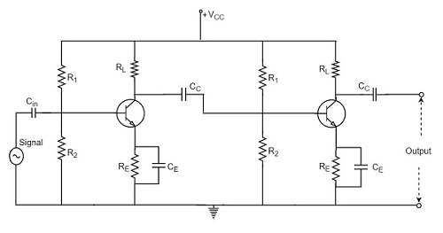
The constructional details of a two-stage RC coupled transistor amplifier circuit are as follows. The two stage amplifier circuit has two transistors, connected in CE configuration and a common power supply VCC is used. The potential divider network R1 and R2 and the resistor Re form the biasing and stabilization network. The emitter by-pass capacitor Ce offers a low reactance path to the signal.
The resistor RL is used as a load impedance. The input capacitor Cin present at the initial stage of the amplifier couples AC signal to the base of the transistor. The capacitor CC is the coupling capacitor that connects two stages and prevents DC interference between the stages and controls the shift of operating point. The figure below shows the circuit diagram of RC coupled amplifier.
Operation of RC Coupled Amplifier
When an AC input signal is applied to the base of first transistor, it gets amplified and appears at the collector load RL which is then passed through the coupling capacitor CC to the next stage. This becomes the input of the next stage, whose amplified output again appears across its collector load. Thus the signal is amplified in stage by stage action.
The important point that has to be noted here is that the total gain is less than the product of the gains of individual stages. This is because when a second stage is made to follow the first stage, the effective load resistance of the first stage is reduced due to the shunting effect of the input resistance of the second stage. Hence, in a multistage amplifier, only the gain of the last stage remains unchanged.
As we consider a two stage amplifier here, the output phase is same as input. Because the phase reversal is done two times by the two stage CE configured amplifier circuit.
Frequency Response of RC Coupled Amplifier
Frequency response curve is a graph that indicates the relationship between voltage gain and function of frequency. The frequency response of a RC coupled amplifier is as shown in the following graph.
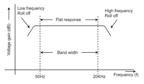
From the above graph, it is understood that the frequency rolls off or decreases for the frequencies below 50Hz and for the frequencies above 20 KHz. whereas the voltage gain for the range of frequencies between 50Hz and 20 KHz is constant.
We know that,
$$X_C = \frac{1}{2 \pi f_c}$$
It means that the capacitive reactance is inversely proportional to the frequency.
At Low frequencies (i.e. below 50 Hz)
The capacitive reactance is inversely proportional to the frequency. At low frequencies, the reactance is quite high. The reactance of input capacitor Cin and the coupling capacitor CC are so high that only small part of the input signal is allowed. The reactance of the emitter by pass capacitor CE is also very high during low frequencies. Hence it cannot shunt the emitter resistance effectively. With all these factors, the voltage gain rolls off at low frequencies.
At High frequencies (i.e. above 20 KHz)
Again considering the same point, we know that the capacitive reactance is low at high frequencies. So, a capacitor behaves as a short circuit, at high frequencies. As a result of this, the loading effect of the next stage increases, which reduces the voltage gain. Along with this, as the capacitance of emitter diode decreases, it increases the base current of the transistor due to which the current gain (β) reduces. Hence the voltage gain rolls off at high frequencies.
At Mid-frequencies (i.e. 50 Hz to 20 KHz)
The voltage gain of the capacitors is maintained constant in this range of frequencies, as shown in figure. If the frequency increases, the reactance of the capacitor CC decreases which tends to increase the gain. But this lower capacitance reactive increases the loading effect of the next stage by which there is a reduction in gain.
Due to these two factors, the gain is maintained constant.
Advantages of RC Coupled Amplifier
The following are the advantages of RC coupled amplifier.
The frequency response of RC amplifier provides constant gain over a wide frequency range, hence most suitable for audio applications.
The circuit is simple and has lower cost because it employs resistors and capacitors which are cheap.
It becomes more compact with the upgrading technology.
Disadvantages of RC Coupled Amplifier
The following are the disadvantages of RC coupled amplifier.
The voltage and power gain are low because of the effective load resistance.
They become noisy with age.
Due to poor impedance matching, power transfer will be low.
Applications of RC Coupled Amplifier
The following are the applications of RC coupled amplifier.
They have excellent audio fidelity over a wide range of frequency.
Widely used as Voltage amplifiers
Due to poor impedance matching, RC coupling is rarely used in the final stages.
