- Transistors - Overview
- Transistor Configurations
- Transistor Regions of Operation
- Transistor Load Line Analysis
- Operating Point
- Transistor as an Amplifier
- Transistor Biasing
- Methods of Transistor Biasing
- Bias Compensation
- Amplifiers
- Basic Amplifier
- Classification of Amplifiers
- Based on Configurations
- Multi-Stage Transistor Amplifier
- RC Coupling Amplifier
- Transformer Coupled Amplifier
- Direct Coupled Amplifier
- Power Amplifiers
- Classification of Power Amplifiers
- Class A Power Amplifiers
- Transformer Coupled Class A Power Amplifier
- Push-Pull Class A Power Amplifier
- Class B Power Amplifier
- Class AB and C Power Amplifiers
- Tuned Amplifiers
- Types of Tuned Amplifiers
- Feedback Amplifiers
- Negative Feedback Amplifiers
- Emitter Follower & Darlington Amplifier
- Noise in Amplifiers
- Amplifiers Useful Resources
- Amplifiers - Quick Guide
- Amplifiers - Useful Resources
- Amplifiers - Discussion
Push-Pull Class A Power Amplifier
So far, we have seen two types of class A power amplifiers. The main problems that should be dealt with are low power output and efficiency. It is possible to obtain greater power output and efficiency than that of the Class A amplifier by using a combinational transistor pair called as Push-Pull configuration.
In this circuit, we use two complementary transistors in the output stage with one transistor being an NPN or N-channel type while the other transistor is a PNP or P-channel (the complement) type connected in order to operate them like PUSH a transistor to ON and PULL another transistor to OFF at the same time. This push-pull configuration can be made in class A, class B, class C or class AB amplifiers.
Construction of Push-Pull Class A Power Amplifier
The construction of the class A power amplifier circuit in push-pull configuration is shown as in the figure below. This arrangement mainly reduces the harmonic distortion introduced by the non-linearity of the transfer characteristics of a single transistor amplifier.
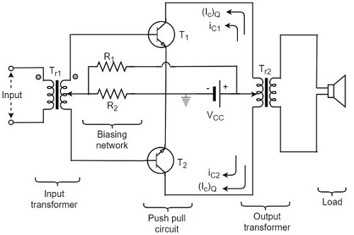
In Push-pull arrangement, the two identical transistors T1 and T2 have their emitter terminals shorted. The input signal is applied to the transistors through the transformer Tr1 which provides opposite polarity signals to both the transistor bases. The collectors of both the transistors are connected to the primary of output transformer Tr2. Both the transformers are center tapped. The VCC supply is provided to the collectors of both the transistors through the primary of the output transformer.
The resistors R1 and R2 provide the biasing arrangement. The load is generally a loudspeaker which is connected across the secondary of the output transformer. The turns ratio of the output transformer is chosen in such a way that the load is well matched with the output impedance of the transistor. So maximum power is delivered to the load by the amplifier.
Circuit Operation
The output is collected from the output transformer Tr2. The primary of this transformer Tr2 has practically no dc component through it. The transistors T1 and T2 have their collectors connected to the primary of transformer Tr2 so that their currents are equal in magnitude and flow in opposite directions through the primary of transformer Tr2.
When the a.c. input signal is applied, the base of transistor T1 is more positive while the base of transistor T2 is less positive. Hence the collector current ic1 of transistor T1 increases while the collector current ic2 of transistor T2 decreases. These currents flow in opposite directions in two halves of the primary of output transformer. Moreover, the flux produced by these currents will also be in opposite directions.
Hence, the voltage across the load will be induced voltage whose magnitude will be proportional to the difference of collector currents i.e.
$$(i_{c1} - i_{c2})$$
Similarly, for the negative input signal, the collector current ic2 will be more than ic1. In this case, the voltage developed across the load will again be due to the difference
$$(i_{c1} - i_{c2})$$
As $i_{c2} > i_{c1}$
The polarity of voltage induced across load will be reversed.
$$i_{c1} - i_{c2} = i_{c1} + (-i_{c2})$$
To have a better understanding, let us consider the below figure.
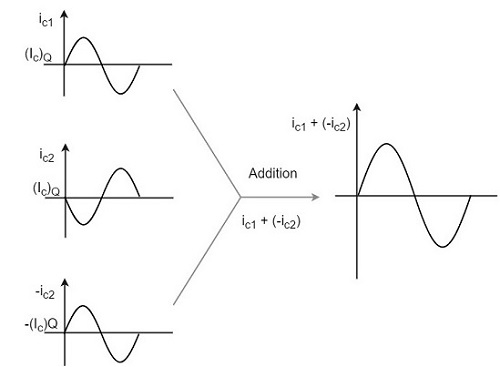
The overall operation results in an a.c. voltage induced in the secondary of output transformer and hence a.c. power is delivered to that load.
It is understood that, during any given half cycle of input signal, one transistor is being driven (or pushed) deep into conduction while the other being non-conducting (pulled out). Hence the name Push-pull amplifier. The harmonic distortion in Push-pull amplifier is minimized such that all the even harmonics are eliminated.
Advantages
The advantages of class A Push-pull amplifier are as follows
High a.c. output is obtained.
The output is free from even harmonics.
The effect of ripple voltages are balanced out. These are present in the power supply due to inadequate filtering.
Disadvantages
The disadvantages of class A Push-pull amplifier are as follows
- The transistors are to be identical, to produce equal amplification.
- Center-tapping is required for the transformers.
- The transformers are bulky and costly.
