- Transistors - Overview
- Transistor Configurations
- Transistor Regions of Operation
- Transistor Load Line Analysis
- Operating Point
- Transistor as an Amplifier
- Transistor Biasing
- Methods of Transistor Biasing
- Bias Compensation
- Amplifiers
- Basic Amplifier
- Classification of Amplifiers
- Based on Configurations
- Multi-Stage Transistor Amplifier
- RC Coupling Amplifier
- Transformer Coupled Amplifier
- Direct Coupled Amplifier
- Power Amplifiers
- Classification of Power Amplifiers
- Class A Power Amplifiers
- Transformer Coupled Class A Power Amplifier
- Push-Pull Class A Power Amplifier
- Class B Power Amplifier
- Class AB and C Power Amplifiers
- Tuned Amplifiers
- Types of Tuned Amplifiers
- Feedback Amplifiers
- Negative Feedback Amplifiers
- Emitter Follower & Darlington Amplifier
- Noise in Amplifiers
- Amplifiers Useful Resources
- Amplifiers - Quick Guide
- Amplifiers - Useful Resources
- Amplifiers - Discussion
Basic Amplifier
We hope that you have gained sufficient knowledge on operating point, its stability and the compensation techniques in the previous chapter. Let us now try to understand the fundamental concepts of a basic amplifier circuit.
An electronic signal contains some information which cannot be utilized if doesnt have proper strength. The process of increasing the signal strength is called as Amplification. Almost all electronic equipment must include some means for amplifying the signals. We find the use of amplifiers in medical devices, scientific equipment, automation, military tools, communication devices, and even in household equipment.
Amplification in practical applications is done using Multi-stage amplifiers. A number of single-stage amplifiers are cascaded to form a Multi-stage amplifier. Let us see how a single-stage amplifier is built, which is the basic for a Multi-stage amplifier.
Single-stage Transistor Amplifier
When only one transistor with associated circuitry is used for amplifying a weak signal, the circuit is known as single-stage amplifier.
Analyzing the working of a Single-stage amplifier circuit, makes us easy to understand the formation and working of Multi-stage amplifier circuits. A Single stage transistor amplifier has one transistor, bias circuit and other auxiliary components. The following circuit diagram shows how a single stage transistor amplifier looks like.
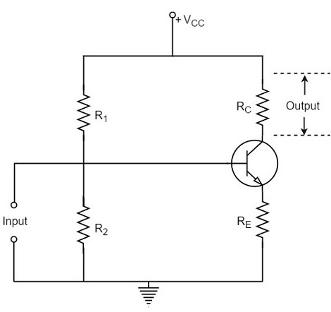
When a weak input signal is given to the base of the transistor as shown in the figure, a small amount of base current flows. Due to the transistor action, a larger current flows in the collector of the transistor. (As the collector current is β times of the base current which means IC = βIB). Now, as the collector current increases, the voltage drop across the resistor RC also increases, which is collected as the output.
Hence a small input at the base gets amplified as the signal of larger magnitude and strength at the collector output. Hence this transistor acts as an amplifier.
Practical Circuit of a Transistor Amplifier
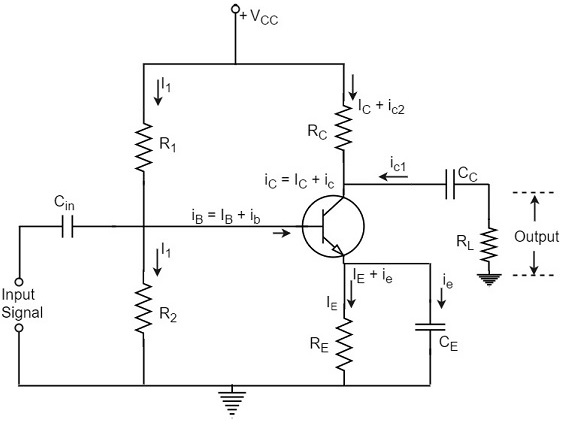
The circuit of a practical transistor amplifier is as shown below, which represents a voltage divider biasing circuit.
The various prominent circuit elements and their functions are as described below.
Biasing Circuit
The resistors R1, R2 and RE form the biasing and stabilization circuit, which helps in establishing a proper operating point.
Input Capacitor Cin
This capacitor couples the input signal to the base of the transistor. The input capacitor Cin allows AC signal, but isolates the signal source from R2. If this capacitor is not present, the input signal gets directly applied, which changes the bias at R2.
Coupling Capacitor CC
This capacitor is present at the end of one stage and connects it to the other stage. As it couples two stages it is called as coupling capacitor. This capacitor blocks DC of one stage to enter the other but allows AC to pass. Hence it is also called as blocking capacitor.
Due to the presence of coupling capacitor CC, the output across the resistor RL is free from the collectors DC voltage. If this is not present, the bias conditions of the next stage will be drastically changed due to the shunting effect of RC, as it would come in parallel to R2 of the next stage.
Emitter by-pass capacitor CE
This capacitor is employed in parallel to the emitter resistor RE. The amplified AC signal is by passed through this. If this is not present, that signal will pass through RE which produces a voltage drop across RE that will feedback the input signal reducing the output voltage.
The Load resistor RL
The resistance RL connected at the output is known as Load resistor. When a number of stages are used, then RL represents the input resistance of the next stage.
Various Circuit currents
Let us go through various circuit currents in the complete amplifier circuit. These are already mentioned in the above figure.
Base Current
When no signal is applied in the base circuit, DC base current IB flows due to biasing circuit. When AC signal is applied, AC base current ib also flows. Therefore, with the application of signal, total base current iB is given by
$$i_B = I_B + i_b$$
Collector Current
When no signal is applied, a DC collector current IC flows due to biasing circuit. When AC signal is applied, AC collector current ic also flows. Therefore, the total collector current iC is given by
$$i_C = I_C + i_c$$
Where
$I_C = \beta I_B$ = zero signal collecor current
$i_c = \beta i_b$ = collecor current due to signal
Emitter Current
When no signal is applied, a DC emitter current IE flows. With the application of signal, total emitter current iE is given by
$$i_E = I_E + i_e$$
It should be remembered that
$$I_E = I_B + I_C$$
$$i_e = i_b + i_c$$
As base current is usually small, it is to be noted that
$I_E \cong I_C$ and $i_e \cong i_c$
These are the important considerations for the practical circuit of transistor amplifier. Now let us know about the classification of Amplifiers.
