- Pulse Circuits Time Base Generators
- Time Base Generators (Overview)
- Types of Time Base Generators
- Bootstrap Time Base Generator
- Miller Sweep Generator
- Pulse Circuits Sweep Circuits
- Unijunction Transistor
- UJT as Relaxation Oscillator
- Pulse Circuits - Synchronization
- Pulse Circuits - Blocking Oscillators
- Pulse Circuits Sampling Gates
- Pulse Circuits - Sampling Gates
- Unidirectional Sampling Gate
- Unidirectional with More Inputs
- Bidirectional Sampling Gates
- Pulse Circuits Useful Resources
- Pulse Circuits - Quick Guide
- Pulse Circuits - Useful Resources
- Pulse Circuits - Discussion
Unidirectional Sampling Gate
After going through the concept of sampling gates, let us now try to understand the types of sampling gates. Unidirectional sampling gates can pass either positive or negative going pulses through them. They are constructed using diodes.
A unidirectional sampling gate circuit consists of a capacitor C, a diode D and two resistors R1 and RL. The signal input is given to the capacitor and the control input is given to the resistor R1. The output is taken across the load resistor RL. The circuit is as shown below.
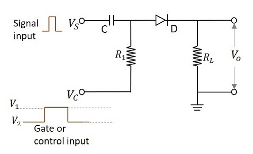
According to the functioning of a diode, it conducts only when the anode of the diode is more positive than the cathode of the diode. If the diode has positive signal at its input, it conducts. The time period in which the gate signal is ON, is the transmission period. Hence it is during that period in which the input signal is transmitted. Otherwise the transmission is not possible.
The following figure shows the time periods of the input signal and the gate signal.
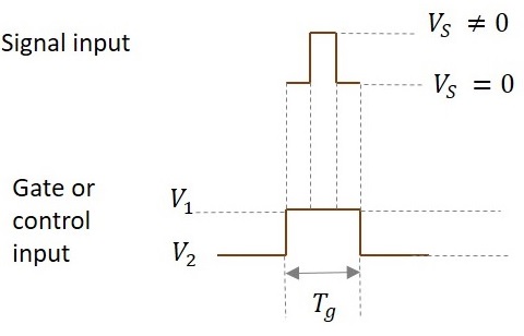
The input signal is transmitted only for the time period during which gate is ON as shown in the figure.
From the circuit we have,
The anode of the diode is applied with the two signals (VS and VC). If the voltage at the anode is indicated as VP and the voltage at the cathode is indicated as VN then the output voltage is obtained as
$$V_o = V_P = (V_S + V_C) > V_N$$
So the diode is in forward biased condition.
$$V_O = V_S + V_1 > V_N$$
Then
$$V_O = V_S$$
When V1 = 0,
Then
$$V_O = V_S + V_1 \: Which \: means \: V_O = V_S$$
Ideal value of V1 = 0.
So, if V1 = 0, the entire input signal appears at output. If the value of V1 is negative, then some of the input is lost and if V1 is positive, additional signal along with input appears at the output.
This whole thing happens during transmission period.
During non-transmission period,
$$V_O = 0$$
As diode is in reverse biased condition
When voltage on anode is less than voltage on cathode,
$$V_S + V_C < 0 \: Volts$$
During non-transmission period,
$$V_C = V_2$$
$$V_S + V_2 < 0$$
Magnitude of V2 should be very high than Vs.
$$|V_2| ≫ V_S$$
Because for the diode to be in reverse bias, the sum of the voltages VS and VC should be negative. VC (which is V2 now) should be as negative as possible so that though VS is positive, the sum of both the voltages should yield a negative result.
Special Cases
Now, lets see a few cases for different values of input voltages where the control voltage is of some negative value.
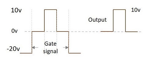
Case 1
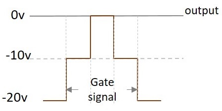
Let us take an example where VS = 10V and VC = -10v (V1) to -20v (V2)
Now, when these two signals are applied, (VS and VC) then the voltage at anode will be
$$V_P = V_S + V_C$$
As this is about transmission period, only V1 is considered for VC.
$$V_O = (10V) + (-10V) = 0V$$
Hence the output will be a zero, though some amount of input voltage is being applied. The following figure explains this point.
Case 2
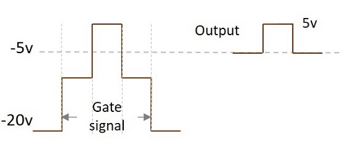
Let us take an example where VS = 10V and VC = -5v (V1) to -20v (V2)
Now, when these two signals are applied, (VS and VC) then the voltage at anode will be
$$V_P = V_S + V_C$$
As this is about transmission period, only V1 is considered for VC.
$$V_O = (10V) + (-5V) = 5V$$
Hence the output will be 5 V. The following figure explains this point.
Case 3
Let us take an example where VS = 10V and VC = 0v (V1) to -20v (V2)
Now, when these two signals are applied, (VS and VC) then the voltage at anode will be
$$V_P = V_S + V_C$$
As this is about transmission period, only V1 is considered for VC.
$$V_O = (10V) + (0V) = 10V$$
Hence the output will be a 10 V. The following figure explains this point.
Case 4
Let us take an example where VS = 10V and VC = 5v (V1) to -20v (V2)
Now, when these two signals are applied, (VS and VC) then the voltage at anode will be
$$V_P = V_S + V_C$$
As this is about transmission period, only V1 is considered for VC.
$$V_O = (10V) + (5V) = 15V$$
Hence the output will be a 15 V.
The output voltage gets affected by the control voltage applied. This voltage adds up to the input to produce the output. Hence it affects the output.
The following figure shows the superimposition of both the signals.
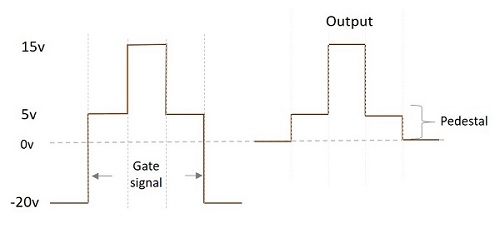
We can observe that during the time when only gate voltage is applied, the output will be 5v. When both the signals are applied, VP appears as VO. During the non-transmission period, output is 0v.
As it is observed from the above figure, the difference in the output signals during transmission period and non-transmission period, though (with VS = 0) input signal is not applied, is called as Pedestal. This pedestal can be positive or negative. In this example, we get a positive pedestal in the output.
Effect of RC on Control voltage
If the input signal is applied before the control voltage reaches the steady state, there occurs some distortion in the output.
We get the correct output only when the input signal is given when control signal is 0v. This 0v is the stable value. If the input signal is given before that, distortion occurs.
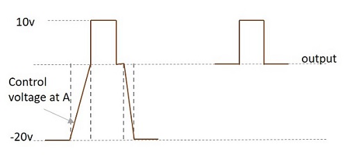
The slow rise in the control voltage at A is due to the RC circuit present. The time constant which is the result of RC affects the shape of this waveform.
Pros and Cons of Unidirectional Sampling Gates
Let us have a look at the advantages and disadvantages of unidirectional sampling gate.
Advantages
The circuitry is simple.
Time delay between input and output is too low.
It can be extended to more number of inputs.
No current is drawn during non-transmission period. Hence under quiescent condition, no power dissipation is present.
Disadvantages
Theres interaction between control and input signals (VC and VS)
As the number of inputs increase, the loading on control input increases.
Output is sensitive to control input voltage V1 (upper level of VC)
Only one input should be applied at one instant of time.
Because of slow rise time of the control signal, the output may get distorted, if the input signal is applied before reaching the steady state.
