- Pulse Circuits Time Base Generators
- Time Base Generators (Overview)
- Types of Time Base Generators
- Bootstrap Time Base Generator
- Miller Sweep Generator
- Pulse Circuits Sweep Circuits
- Unijunction Transistor
- UJT as Relaxation Oscillator
- Pulse Circuits - Synchronization
- Pulse Circuits - Blocking Oscillators
- Pulse Circuits Sampling Gates
- Pulse Circuits - Sampling Gates
- Unidirectional Sampling Gate
- Unidirectional with More Inputs
- Bidirectional Sampling Gates
- Pulse Circuits Useful Resources
- Pulse Circuits - Quick Guide
- Pulse Circuits - Useful Resources
- Pulse Circuits - Discussion
Pulse Circuits - Astable Multivibrator
An astable multivibrator has no stable states. Once the Multivibrator is ON, it just changes its states on its own after a certain time period which is determined by the RC time constants. A dc power supply or Vcc is given to the circuit for its operation.
Construction of Astable Multivibrator
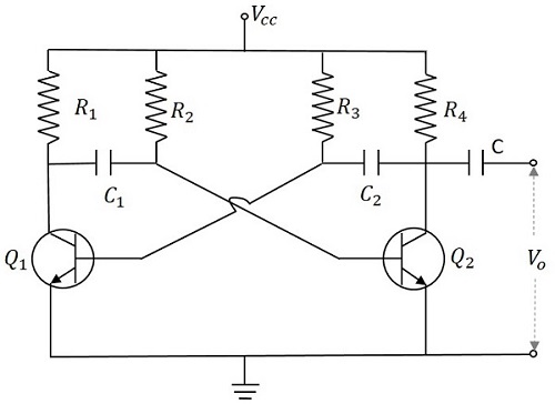
Two transistors named Q1 and Q2 are connected in feedback to one another. The collector of transistor Q1 is connected to the base of transistor Q2 through the capacitor C1 and vice versa. The emitters of both the transistors are connected to the ground. The collector load resistors R1 and R4 and the biasing resistors R2 and R3 are of equal values. The capacitors C1 and C2 are of equal values.
The following figure shows the circuit diagram for Astable Multivibrator.
Operation of Astable Multivibrator
When Vcc is applied, the collector current of the transistors increase. As the collector current depends upon the base current,
$$I_c = \beta I_B$$
As no transistor characteristics are alike, one of the two transistors say Q1 has its collector current increase and thus conducts. The collector of Q1 is applied to the base of Q2 through C1. This connection lets the increased negative voltage at the collector of Q1 to get applied at the base of Q2 and its collector current decreases. This continuous action makes the collector current of Q2 to decrease further. This current when applied to the base of Q1 makes it more negative and with the cumulative actions Q1 gets into saturation and Q2 to cut off. Thus the output voltage of Q1 will be VCE (sat) and Q2 will be equal to VCC.
The capacitor C1 charges through R1 and when the voltage across C1 reaches 0.7v, this is enough to turn the transistor Q2 to saturation. As this voltage is applied to the base of Q2, it gets into saturation, decreasing its collector current. This reduction of voltage at point B is applied to the base of transistor Q1 through C2 which makes the Q1 reverse bias. A series of these actions turn the transistor Q1 to cut off and transistor Q2 to saturation. Now point A has the potential VCC. The capacitor C2 charges through R2. The voltage across this capacitor C2 when gets to 0.7v, turns on the transistor Q1 to saturation.
Hence the output voltage and the output waveform are formed by the alternate switching of the transistors Q1 and Q2. The time period of these ON/OFF states depends upon the values of biasing resistors and capacitors used, i.e., on the RC values used. As both the transistors are operated alternately, the output is a square waveform, with the peak amplitude of VCC.
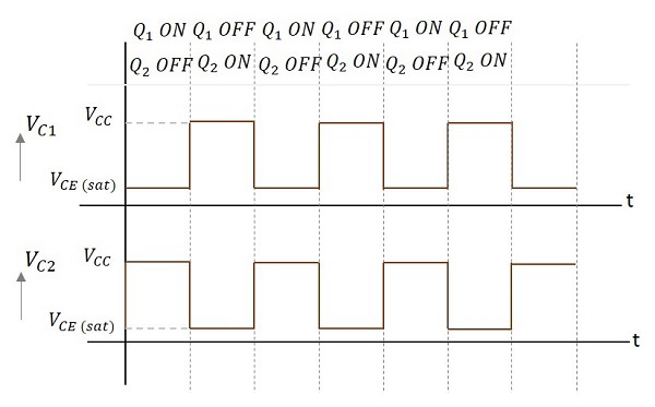
Waveforms
The output waveforms at the collectors of Q1 and Q2 are shown in the following figures.
Frequency of Oscillations
The ON time of transistor Q1 or the OFF time of transistor Q2 is given by
t1 = 0.69R1C1
Similarly, the OFF time of transistor Q1 or ON time of transistor Q2 is given by
t2 = 0.69R2C2
Hence, total time period of square wave
t = t1 + t2 = 0.69(R1C1 + R2C2)
As R1 = R2 = R and C1 = C2 = C, the frequency of square wave will be
$$f = \frac{1}{t} = \frac{1}{1.38 R C} = \frac{0.7}{RC}$$
Advantages
The advantages of using an astable multivibrator are as follows −
- No external triggering required.
- Circuit design is simple
- Inexpensive
- Can function continuously
Disadvantages
The drawbacks of using an astable multivibrator are as follows −
- Energy absorption is more within the circuit.
- Output signal is of low energy.
- Duty cycle less than or equal to 50% cant be achieved.
Applications
Astable Multivibrators are used in many applications such as amateur radio equipment, Morse code generators, timer circuits, analog circuits, and TV systems.
