- Pulse Circuits Time Base Generators
- Time Base Generators (Overview)
- Types of Time Base Generators
- Bootstrap Time Base Generator
- Miller Sweep Generator
- Pulse Circuits Sweep Circuits
- Unijunction Transistor
- UJT as Relaxation Oscillator
- Pulse Circuits - Synchronization
- Pulse Circuits - Blocking Oscillators
- Pulse Circuits Sampling Gates
- Pulse Circuits - Sampling Gates
- Unidirectional Sampling Gate
- Unidirectional with More Inputs
- Bidirectional Sampling Gates
- Pulse Circuits Useful Resources
- Pulse Circuits - Quick Guide
- Pulse Circuits - Useful Resources
- Pulse Circuits - Discussion
Pulse Circuits - Multivibrator Overview
A multivibrator circuit is nothing but a switching circuit. It generates non-sinusoidal waves such as Square waves, Rectangular waves and Saw tooth waves etc. Multivibrators are used as frequency generators, frequency dividers and generators of time delays and also as memory elements in computers etc.
A Transistor basically functions as an amplifier in its linear region. If a transistor amplifier output stage is joined with the previous amplifier stage, such a connection is said to be coupled. If a resistor is used in coupling two stages of such an amplifier circuit, it is called as Resistance coupled amplifier. For more details, refer to the AMPLIFIERS tutorial.
What is a Multivibrator?
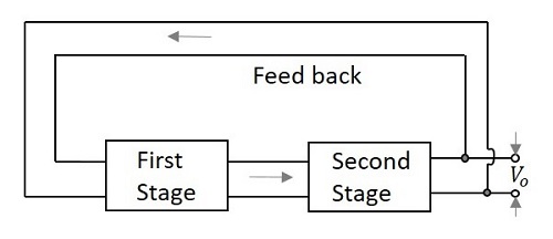
According to the definition, A Multivibrator is a two-stage resistance coupled amplifier with positive feedback from the output of one amplifier to the input of the other.
Two transistors are connected in feedback so that one controls the state of the other. Hence the ON and OFF states of the whole circuit, and the time periods for which the transistors are driven into saturation or cut off are controlled by the conditions of the circuit.
The following figure shows the block diagram of a Multivibrator.
Types of Multivibrators
There are two possible states of a Multivibrator. In first stage, the transistor Q1 turns ON while the transistor Q2 turns OFF. In second stage, the transistor Q1 turns OFF while the transistor Q2 turns ON. These two states are interchanged for certain time periods depending upon the circuit conditions.
Depending upon the manner in which these two states are interchanged, the Multivibrators are classified into three types. They are
Astable Multivibrator
An Astable Multivibrator is such a circuit that it automatically switches between the two states continuously without the application of any external pulse for its operation. As this produces a continuous square wave output, it is called as a Free-running Multivibrator. The dc power source is a common requirement.
The time period of these states depends upon the time constants of the components used. As the Multivibrator keeps on switching, these states are known as quasi-stable or halfstable states. Hence there are two quasi-stable states for an Astable Multivibrator.
Monostable Multivibrator
A Monostable Multivibrator has a stable state and a quasi-stable state. This has a trigger input to one transistor. So, one transistor changes its state automatically, while the other one needs a trigger input to change its state.
As this Multivibrator produces a single output for each trigger pulse, this is known as One-shot Multivibrator. This Multivibrator cannot stay in quasi-stable state for a longer period while it stays in stable state until the trigger pulse is received.
Bistable Multivibrator
A Bistable Multivibrator has both the two states stable. It requires two trigger pulses to be applied to change the states. Until the trigger input is given, this Multivibrator cannot change its state. Its also known as flip-flop multivibrator.
As the trigger pulse sets or resets the output, and as some data, i.e., either high or low is stored until it is disturbed, this Multivibrator can be called as a Flip-flop. To know more about flip-flops, refer our DIGITAL CIRCUITS tutorial at: https://www.tutorialspoint.com/digital_circuits/index.htm
To get a clear idea on the above discussion, let us have a look at the following figure.
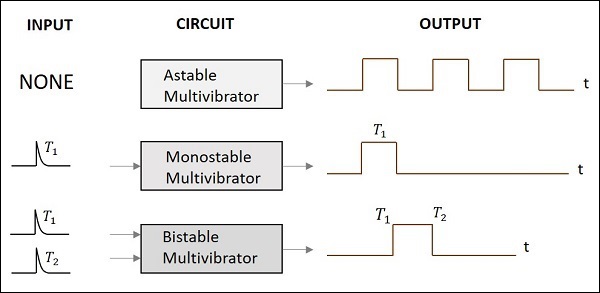
All these three Multivibrators are clearly discussed in the next chapters.
