- Pulse Circuits Time Base Generators
- Time Base Generators (Overview)
- Types of Time Base Generators
- Bootstrap Time Base Generator
- Miller Sweep Generator
- Pulse Circuits Sweep Circuits
- Unijunction Transistor
- UJT as Relaxation Oscillator
- Pulse Circuits - Synchronization
- Pulse Circuits - Blocking Oscillators
- Pulse Circuits Sampling Gates
- Pulse Circuits - Sampling Gates
- Unidirectional Sampling Gate
- Unidirectional with More Inputs
- Bidirectional Sampling Gates
- Pulse Circuits Useful Resources
- Pulse Circuits - Quick Guide
- Pulse Circuits - Useful Resources
- Pulse Circuits - Discussion
Pulse Circuits - Signal
A Signal not only carries information but it also represents the condition of the circuit. The functioning of any circuit can be studies by the signal it produces. Hence, we will start this tutorial with a brief introduction to signals.
Electronic Signal
An electronic signal is similar to a normal signal we come across, which indicates something or which informs about something. The graphical representation of an electronic signal gives information regarding the periodical changes in the parameters such as amplitude or phase of the signal. It also provides information regarding the voltage, frequency, time period, etc.
This representation brings some shape to the information conveyed or to the signal received. Such a shape of the signal when formed according to a certain variation, can be given different names, such as sinusoidal signal, triangular signal, saw tooth signal and square wave signal etc.
These signals are mainly of two types named as Unidirectional and Bidirectional signals.
Unidirectional Signal − The signal when flows only in one direction, which is either positive or negative, such a signal is termed as Unidirectional signal.
Example − Pulse signal.
Bidirectional Signal − The signal when alters in both positive and negative directions crossing the zero point, such a signal is termed as a Bidirectional signal.
Example − Sinusoidal signal.
In this chapter, we are going to discuss pulse signals and their characteristic features.
Pulse Signal
A Pulse shape is formed by a rapid or sudden transient change from a baseline value to a higher or lower level value, which returns to the same baseline value after a certain time period. Such a signal can be termed as Pulse Signal.
The following illustration shows a series of pulses.
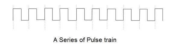
A Pulse signal is a unidirectional, non-sinusoidal signal which is similar to a square signal but it is not symmetrical like a square wave. A series of continuous pulse signals is simply called as a pulse train. A train of pulses indicate a sudden high level and a sudden low level transition from a baseline level which can be understood as ON/OFF respectively.
Hence a pulse signal indicates ON & OFF of the signal. If an electric switch is given a pulse input, it gets ON/OFF according to the pulse signal given. These switches which produce the pulse signals can be discussed later.
Terms Related to Pulse signals
There are few terms related to pulse signals which one should know. These can be understood with the help of the following figure.
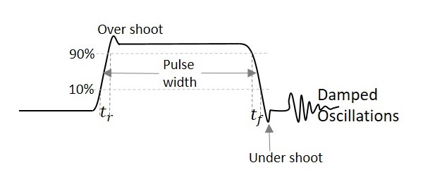
From the above figure,
Pulse width − Length of the pulse
Period of a waveform − Measurement from any point on one cycle to the same point on next cycle
Duty cycle − Ratio of the pulse width to the period
Rise time − Time it takes to rise from 10% to 90% of its maximum amplitude.
Fall time − Time signal takes to fall from 90% to 10% of its maximum amplitude.
Overshoot − Said to be occurred when leading edge of a waveform exceeds its normal maximum value.
Undershoot − Said to be occurred when trailing edge of a waveform exceeds its normal maximum value.
Ringing − Both undershoot and overshoot are followed by damped oscillations known as ringing.
The damped oscillations are the signal variations that indicate the decreasing amplitude and frequency of the signal which are of no use and unwanted. These oscillations are simple disturbances known as ringing.
In the next chapter, we will explain the concept of switching in electronics done using BJTs. We had already discussed switching using diodes in our ELECTRONIC CIRCUITS tutorial. Please refer.
