- Pulse Circuits Time Base Generators
- Time Base Generators (Overview)
- Types of Time Base Generators
- Bootstrap Time Base Generator
- Miller Sweep Generator
- Pulse Circuits Sweep Circuits
- Unijunction Transistor
- UJT as Relaxation Oscillator
- Pulse Circuits - Synchronization
- Pulse Circuits - Blocking Oscillators
- Pulse Circuits Sampling Gates
- Pulse Circuits - Sampling Gates
- Unidirectional Sampling Gate
- Unidirectional with More Inputs
- Bidirectional Sampling Gates
- Pulse Circuits Useful Resources
- Pulse Circuits - Quick Guide
- Pulse Circuits - Useful Resources
- Pulse Circuits - Discussion
Bootstrap Time Base Generator
A bootstrap sweep generator is a time base generator circuit whose output is fed back to the input through the feedback. This will increase or decrease the input impedance of the circuit. This process of bootstrapping is used to achieve constant charging current.
Construction of Bootstrap Time Base Generator
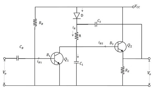
The boot strap time base generator circuit consists of two transistors, Q1 which acts as a switch and Q2 which acts as an emitter follower. The transistor Q1 is connected using an input capacitor CB at its base and a resistor RB through VCC. The collector of the transistor Q1 is connected to the base of the transistor Q2. The collector of Q2 is connected to VCC while its emitter is provided with a resistor RE across which the output is taken.
A diode D is taken whose anode is connected to VCC while cathode is connected to the capacitor C2 which is connected to the output. The cathode of diode D is also connected to a resistor R which is in turn connected to a capacitor C1. This C1 and R are connected through the base of Q2 and collector of Q1. The voltage that appears across the capacitor C1 provides the output voltage Vo.
The following figure explains the construction of the boot strap time base generator.
Operation of Bootstrap Time Base Generator
Before the application of gating waveform at t = 0, as the transistor gets enough base drive from VCC through RB, Q1 is ON and Q2 is OFF. The capacitor C2 charges to VCC through the diode D. Then a negative trigger pulse from the gating waveform of a Monostable Multivibrator is applied at the base of Q1 which turns Q1 OFF. The capacitor C2 now discharges and the capacitor C1 charges through the resistor R. As the capacitor C2 has large value of capacitance, its voltage levels (charge and discharge) vary at a slower rate. Hence it discharges slowly and maintains a nearly constant value during the ramp generation at the output of Q2.
During the ramp time, the diode D is reverse biased. The capacitor C2 provides a small current IC1 for the capacitor C1 to charge. As the capacitance value is high, though it provides current, it doesnt make much difference in its charge. When Q1 gets ON at the end of ramp time, C1 discharges rapidly to its initial value. This voltage appears across VO. Consequently, the diode D gets forward biased again and the capacitor C2 gets a pulse of current to recover its small charge lost during the charging of C1. Now, the circuit is ready to produce another ramp output.
The capacitor C2 which helps in providing some feedback current to the capacitor C1 acts as a boot strapping capacitor that provides constant current.
Output Waveforms
The output waveforms are obtained as shown in the following figure.
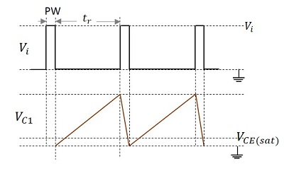
The pulse given at the input and the voltage VC1 which denotes the charging and discharging of the capacitor C1 which contributes the output are shown in the figure above.
Advantage
The main advantage of this boot strap ramp generator is that the output voltage ramp is very linear and the ramp amplitude reaches the supply voltage level.
