- Pulse Circuits Time Base Generators
- Time Base Generators (Overview)
- Types of Time Base Generators
- Bootstrap Time Base Generator
- Miller Sweep Generator
- Pulse Circuits Sweep Circuits
- Unijunction Transistor
- UJT as Relaxation Oscillator
- Pulse Circuits - Synchronization
- Pulse Circuits - Blocking Oscillators
- Pulse Circuits Sampling Gates
- Pulse Circuits - Sampling Gates
- Unidirectional Sampling Gate
- Unidirectional with More Inputs
- Bidirectional Sampling Gates
- Pulse Circuits Useful Resources
- Pulse Circuits - Quick Guide
- Pulse Circuits - Useful Resources
- Pulse Circuits - Discussion
Pulse Circuits - Switch
A Switch is a device that makes or breaks a circuit or a contact. As well, it can convert an analog data into digital data. The main requirements of a switch to be efficient are to be quick and to switch without sparking. The essential parts are a switch and its associated circuitry.
There are three types of Switches. They are −
- Mechanical switches
- Electromechanical switches or Relays
- Electronic switches
Mechanical Switches
The Mechanical Switches are the older type switches, which we previously used. But they had been replaced by Electro-mechanical switches and later on by electronic switches also in a few applications, so as to get over the disadvantages of the former.
The drawbacks of Mechanical Switches are as follows −
- They have high inertia which limits the speed of operation.
- They produce sparks while breaking the contact.
- Switch contacts are made heavy to carry larger currents.
The mechanical switches look as in the figure below.
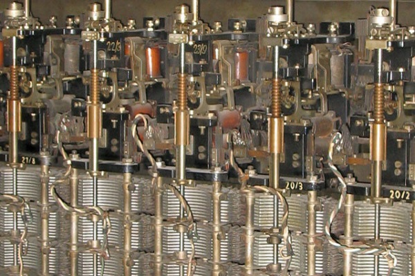
These mechanical switches were replaced by electro-mechanical switches or relays that have good speed of operation and reduce sparking.
Relays
Electromechanical switches are also called as Relays. These switches are partially mechanical and partially electronic or electrical. These are greater in size than electronic switches and lesser in size than mechanical switches.
Construction of a Relay
A Relay is made such that the making of contact supplies power to the load. In the external circuit, we have load power supply for the load and coil power supply for controlling the relay operation. Internally, a lever is connected to the iron yoke with a hard spring to hold the lever up. A Solenoid is connected to the yoke with an operating coil wounded around it. This coil is connected with the coil power supply as mentioned.
The figure below explains the construction and working of a Relay.
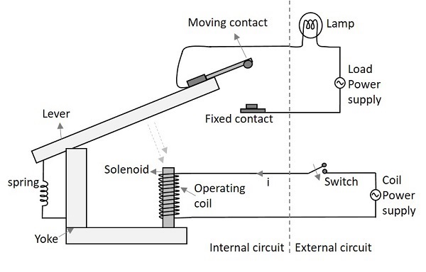
Working of a Relay
When the Switch is closed, an electrical path is established which energizes the solenoid. The lever is connected by a heavy spring which pulls up the lever and holds. The solenoid when gets energized, pulls the lever towards it, against the pulling force of the spring. When the lever gets pulled, the moving contact meets the fixed contact in order to connect the circuit. Thus the circuit connection is ON or established and the lamp glows indicating this.
When the switch is made OFF, the solenoid doesnt get any current and gets de-energized. This leaves the lever without any attraction towards the solenoid. The spring pulls the lever up, which breaks the contact. Thus the circuit connection gets switched OFF.
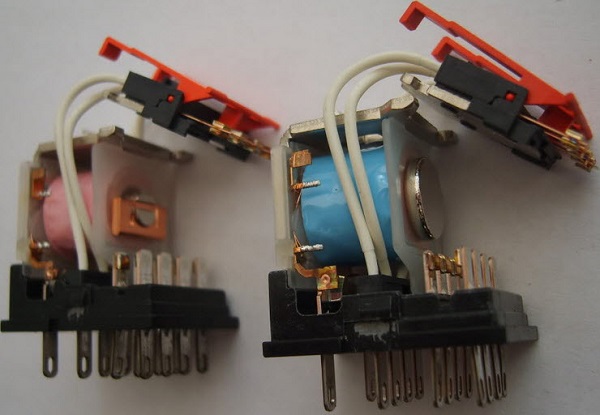
The figure below shows how a practical relay looks like.
Let us now have a look at the advantages and disadvantages of an Electro-magnetic switch.
Advantages
- A relay consumes less energy, even to handle a large power at the load.
- The operator can be at larger distance, even to handle high voltages.
- No Sparking while turning ON or OFF.
Disadvantages
- Slow in operation
- Parts are prone to wear and tear
Types of Latches in Relays
There are many kinds of relays depending upon their mode of operation such as Electromagnetic relay, solid-state relay, thermal relay, hybrid relay, reed relay etc.
The relay makes the connection with the help of a latch, as shown in the following figure.
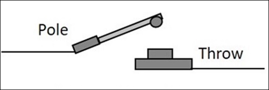
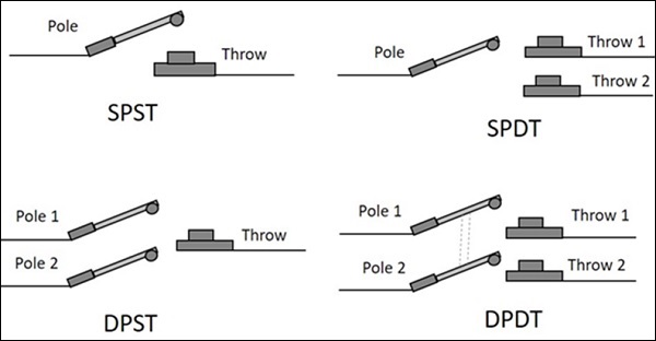
There are four types of latch connections in relays. They are −
Single Pole Single Throw (SPST) − This latch has a single pole and is thrown onto a single throw to make a connection.
Single Pole Double Throw (SPDT) − This latch has a single pole and double throw to make a connection. It has a choice to make connection with two different circuits for which two throws were connected.
Double Pole Single Throw (DPST) − This latch has a double pole and single throw to make a connection. Any of the two circuits can choose to make the connection with the circuit available at the single throw.
Double Pole Double Throw (DPDT) − This latch has a double pole and is thrown onto double throw to make two connections at the same time.
The following figure shows the diagrammatic view of all the four types of latch connections.
Electronic Switch
The next kind of switch to be discussed is the Electronic Switch. As mentioned earlier, transistor is the mostly used electronic switch for its high operating speed and absence of sparking.
The following image shows a practical electronic circuit built to make transistor work as a switch.
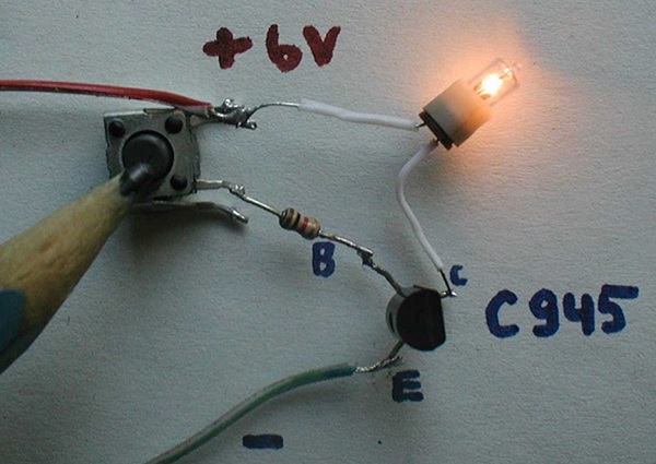
A Transistor works as a switch in ON condition, when it is operated in saturation region. It works as a switch in OFF condition, when it is operated in cut off region. It works as an amplifier in linear region, which lies between transistor and cut off. To have an idea regarding these regions of operation, refer to the transistors chapter from BASIC ELECTRONICS tutorial.
When the external conditions are so robust and high temperatures prevail, then a simple and normal transistor would not do. A special device named as Silicon Control Rectifier, simply SCR is used for such purposes. This will be discussed in detail, in the POWER ELECTRONICS tutorial.
Advantages of an Electronic Switch
There are many advantages of an Electronic switch such as
- Smaller in size
- Lighter in weight
- Sparkles operation
- No moving parts
- Less prone to wear and tear
- Noise less operation
- Faster operation
- Cheaper than other switches
- Less maintenance
- Troublefree service because of solid-state
A transistor is a simple electronic switch that has high operating speed. It is a solid state device and the contacts are all simple and hence the sparking is avoided while in operation. We will discuss the stages of switching operation in a transistor in the next chapter.
