- Pulse Circuits Time Base Generators
- Time Base Generators (Overview)
- Types of Time Base Generators
- Bootstrap Time Base Generator
- Miller Sweep Generator
- Pulse Circuits Sweep Circuits
- Unijunction Transistor
- UJT as Relaxation Oscillator
- Pulse Circuits - Synchronization
- Pulse Circuits - Blocking Oscillators
- Pulse Circuits Sampling Gates
- Pulse Circuits - Sampling Gates
- Unidirectional Sampling Gate
- Unidirectional with More Inputs
- Bidirectional Sampling Gates
- Pulse Circuits Useful Resources
- Pulse Circuits - Quick Guide
- Pulse Circuits - Useful Resources
- Pulse Circuits - Discussion
Pulse Circuits - Monostable Multivibrator
A monostable multivibrator, as the name implies, has only one stable state. When the transistor conducts, the other remains in non-conducting state. A stable state is such a state where the transistor remains without being altered, unless disturbed by some external trigger pulse. As Monostable works on the same principle, it has another name called as One-shot Multivibrator.
Construction of Monostable Multivibrator
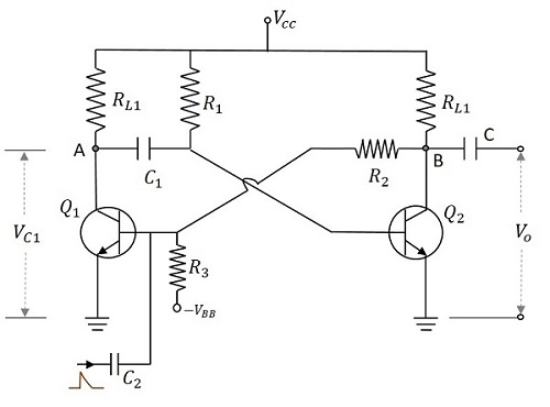
Two transistors Q1 and Q2 are connected in feedback to one another. The collector of transistor Q1 is connected to the base of transistor Q2 through the capacitor C1. The base Q1 is connected to the collector of Q2 through the resistor R2 and capacitor C. Another dc supply voltage VBB is given to the base of transistor Q1 through the resistor R3. The trigger pulse is given to the base of Q1 through the capacitor C2 to change its state. RL1 and RL2 are the load resistors of Q1 and Q2.
One of the transistors, when gets into a stable state, an external trigger pulse is given to change its state. After changing its state, the transistor remains in this quasi-stable state or Meta-stable state for a specific time period, which is determined by the values of RC time constants and gets back to the previous stable state.
The following figure shows the circuit diagram of a Monostable Multivibrator.
Operation of Monostable Multivibrator
Firstly, when the circuit is switched ON, transistor Q1 will be in OFF state and Q2 will be in ON state. This is the stable state. As Q1 is OFF, the collector voltage will be VCC at point A and hence C1 gets charged. A positive trigger pulse applied at the base of the transistor Q1 turns the transistor ON. This decreases the collector voltage, which turns OFF the transistor Q2. The capacitor C1 starts discharging at this point of time. As the positive voltage from the collector of transistor Q2 gets applied to transistor Q1, it remains in ON state. This is the quasi-stable state or Meta-stable state.
The transistor Q2 remains in OFF state, until the capacitor C1 discharges completely. After this, the transistor Q2 turns ON with the voltage applied through the capacitor discharge. This turn ON the transistor Q1, which is the previous stable state.
Output Waveforms
The output waveforms at the collectors of Q1 and Q2 along with the trigger input given at the base of Q1 are shown in the following figures.
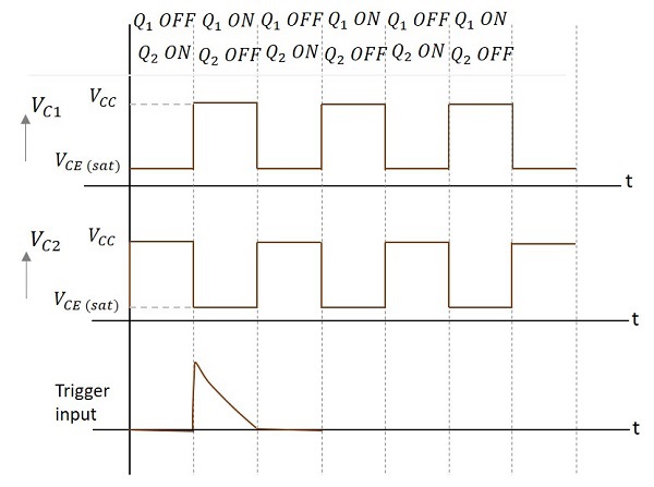
The width of this output pulse depends upon the RC time constant. Hence it depends on the values of R1C1. The duration of pulse is given by
$$T = 0.69R_1 C_1$$
The trigger input given will be of very short duration, just to initiate the action. This triggers the circuit to change its state from Stable state to Quasi-stable or Meta-stable or Semi-stable state, in which the circuit remains for a short duration. There will be one output pulse for one trigger pulse.
Advantages
The advantages of Monostable Multivibrator are as follows −
- One trigger pulse is enough.
- Circuit design is simple
- Inexpensive
Disadvantages
The major drawback of using a monostable multivibrator is that the time between the applications of trigger pulse T has to be greater than the RC time constant of the circuit.
Applications
Monostable Multivibrators are used in applications such as television circuits and control system circuits.
