- Pulse Circuits Time Base Generators
- Time Base Generators (Overview)
- Types of Time Base Generators
- Bootstrap Time Base Generator
- Miller Sweep Generator
- Pulse Circuits Sweep Circuits
- Unijunction Transistor
- UJT as Relaxation Oscillator
- Pulse Circuits - Synchronization
- Pulse Circuits - Blocking Oscillators
- Pulse Circuits Sampling Gates
- Pulse Circuits - Sampling Gates
- Unidirectional Sampling Gate
- Unidirectional with More Inputs
- Bidirectional Sampling Gates
- Pulse Circuits Useful Resources
- Pulse Circuits - Quick Guide
- Pulse Circuits - Useful Resources
- Pulse Circuits - Discussion
Pulse Circuits - Miller Sweep Generator
The transistor Miller time base generator circuit is the popular Miller integrator circuit that produces a sweep waveform. This is mostly used in horizontal deflection circuits.
Let us try to understand the construction and working of a Miller time base generator circuit.
Construction of Miller Sweep Generator
The Miller time base generator circuit consists of a switch and a timing circuit in the initial stage, whose input is taken from the Schmitt gate generator circuit. The amplifier section is the following one which has three stages, first being an emitter follower, second an amplifier and the third one is also an emitter follower.
An emitter follower circuit usually acts as a Buffer amplifier. It has a low output impedance and a high input impedance. The low output impedance lets the circuit drive a heavy load. The high input impedance keeps the circuit from not loading its previous circuit. The last emitter follower section will not load the previous amplifier section. Because of this, the amplifier gain will be high.
The capacitor C placed between the base of Q1 and the emitter of Q3 is the timing capacitor. The values of R and C and the variation in the voltage level of VBB changes the sweep speed. The figure below shows the circuit of a Miller time base generator.
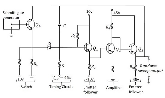
Operation of Miller Sweep Generator
When the output of Schmitt trigger generator is a negative pulse, the transistor Q4 turns ON and the emitter current flows through R1. The emitter is at negative potential and the same is applied at the cathode of the diode D, which makes it forward biased. As the capacitor C is bypassed here, it is not charged.
The application of a trigger pulse, makes the Schmitt gate output high, which in turn, turns the transistor Q4 OFF. Now, a voltage of 10v is applied at the emitter of Q4 that makes the current flow through R1 which also makes the diode D reverse biased. As the transistor Q4 is in cutoff, the capacitor C gets charged from VBB through R and provides a rundown sweep output at the emitter of Q3. The capacitor C discharges through D and transistor Q4 at the end of the sweep.
Considering the effect of capacitance C1, the slope speed or sweep speed error is given by
$$e_s = \frac{V_s}{V} \left( 1- A + \frac{R}{R_i} + \frac{C}{C_i} \right )$$
Applications
Miller sweep circuits are the most commonly used integrator circuit in many devices. It is a widely used saw tooth generator.
