- Pulse Circuits Time Base Generators
- Time Base Generators (Overview)
- Types of Time Base Generators
- Bootstrap Time Base Generator
- Miller Sweep Generator
- Pulse Circuits Sweep Circuits
- Unijunction Transistor
- UJT as Relaxation Oscillator
- Pulse Circuits - Synchronization
- Pulse Circuits - Blocking Oscillators
- Pulse Circuits Sampling Gates
- Pulse Circuits - Sampling Gates
- Unidirectional Sampling Gate
- Unidirectional with More Inputs
- Bidirectional Sampling Gates
- Pulse Circuits Useful Resources
- Pulse Circuits - Quick Guide
- Pulse Circuits - Useful Resources
- Pulse Circuits - Discussion
Pulse Circuits - Synchronization
In any system, having different waveform generators, all of them are required to be operated in synchronism. Synchronization is the process of making two or more waveform generators arrive at some reference point in the cycle exactly at the same time.
Types of Synchronization
Synchronization can be of the following two types −
One-to-one basis
All the generators are operated at a same frequency.
All of them arrive at some reference point in the cycle exactly at the same time.
Sync with frequency division
Generators operate at different frequency which are integral multiples of each other.
All of them arrive at some reference point in the cycle exactly at the same time.
Relaxation devices
Relaxation circuits are the circuits in which the timing interval is established through the gradual charging of a capacitor, the timing interval being terminated by the sudden discharge (relaxation) of a capacitor.
Examples − Multivibrators, sweep circuits, blocking oscillators, etc.
We have observed in the UJT relaxation oscillator circuit that the capacitor stops charging when the negative resistance device such as UJT turns ON. The capacitor then discharges through it to reach its minimum value. Both these points denote the maximum and minimum voltage points of a sweep waveform.
Synchronization in Relaxation Devices
If the high voltage or peak voltage or breakdown voltage of the sweep waveform has to be brought down to a lower level, then an external signal can be applied. This signal to be applied is the synchronized signal whose effect lowers the voltage of peak or breakdown voltage, for the duration of the pulse. A synchronizing pulse is generally applied at the emitter or at the base of a negative resistance device. A pulse train having regularly spaced pulses is applied to achieve synchronization.
Though the synchronizing signal is applied first few pulses will have no effect on the sweep generator as the amplitude of the sweep signal at the occurrence of the pulse, in addition with the amplitude of the pulse is less than VP. Hence the sweep generator runs unsynchronized. The exact moment at which UJT turns ON is determined by the instant ofoccurrence of a pulse. This is the point where the sync signal achieves synchronization with the sweep signal. This can be observed from the following figure.
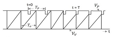
Where,
- TP is the time period of the pulse signal
- TO is the time period of the sweep signal
- VP is the Peak or breakdown voltage
- VV is the Valley or Maintaining voltage
To achieve synchronization, the pulse timing interval TP should be less than the time period of sweep generator TO, so that it terminates the sweep cycle prematurely. The synchronization cannot be achieved if the pulse timing interval TP is greater than the time period of sweep generator TO and also if the amplitude of the pulses is not large enough to bridge the gap between the quiescent breakdown and the sweep voltage, though TP is less than TO.
Frequency Division in Sweep Circuits
In the previous topic, we have observed that synchronization gets achieved when the following conditions are satisfied. They are
When TP < TO
When the amplitude of the pulse is sufficient to terminate each cycle prematurely.
Satisfying these two conditions, though synchronization is achieved, we may often come across a certain interesting pattern in the sweep with regard to sync timing. The following figure illustrates this point.
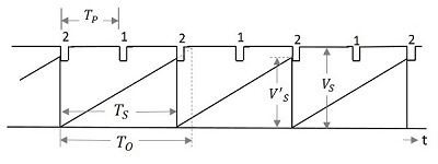
We can observe that the amplitude VS of the sweep after synchronization is less than the unsynchronized amplitude VS. Also the time period TO of the sweep is adjusted according to the time period of the pulse but leaving a cycle in-between. Which means, one sweep cycle is made equal to two pulse cycles. The synchronization is achieved for every alternate cycle, which states
$$T_o > 2T_P$$
The sweep timing TO be restricted to TS and its amplitude is reduced to VS.
As every second pulse is made in synchronism with the sweep cycle, this signal can be understood as a circuit that exhibits frequency division by a factor of 2. Hence the frequency division circuit is obtained by synchronization.
